System for controlling particulate filter temperature

a technology for controlling the temperature of parts and filters, applied in the direction of electric devices, gas pressure propulsion mountings, driver interactions, etc., can solve the problems of unscheduled vehicle maintenance, filter failure, exhaust temperature produced under normal engine operation in such systems, etc., and achieve the effect of promoting appropriate filter regeneration

Inactive Publication Date: 2005-06-07
CUMMINS INC
View PDF28 Cites 100 Cited by
  • Summary
  • Abstract
  • Description
  • Claims
  • Application Information

AI Technical Summary

Benefits of technology

[0010]In accordance with yet another aspect of the present invention, a system for controlling particulate filter temperature comprises an internal combustion engine producing exhaust gas at an exhaust gas port, a particulate filter having an inlet fluidly coupled to the exhaust port of the engine and an outlet, means for determining a temperature of the particulate filter, and a control circuit controlling rotational speed of the engine between an idle speed and a maximum speed, the control circuit increasing the idle speed if the temperature of the particulate filter exceeds a first temperature to thereby cool the particulate filter by increasing exhaust gas flow therethrough.
[0011]In accordance with still another aspect of the present invention, a method of controlling the temperature of a particulate filter coupled to an exhaust port of an internal combustion engine operating at rotational speeds between an idle speed and a maximum speed comprises the steps of determining a temperature of the particulate filter, and increasing the idle speed if the temperature of the particulate filter exceeds a first temperature to thereby cool the particulate filter by increasing a flow rate of engine exhaust gas therethrough.
[0013]In accordance with yet a further aspect of the present invention, a method of controlling the temperature of a particulate filter coupled to an exhaust port of an internal combustion engine coupled to a transmission having a number of automatically selectable gear ratios comprises the steps of determining a temperature of the particulate filter, and commanding automatic shifting of the transmission according to a shift schedule having higher engine speed shift points than those of a default engine speed shift point schedule if the temperature of the particulate filter exceeds a first temperature, causing the engine to resultantly operate at higher engine speeds with correspondingly higher exhaust gas flow through the particulate filter to thereby cool the particulate filter.
[0014]The present invention provides a system for controlling the temperature of a particulate filter in a manner that protects the filter from damage resulting from excessively high temperatures and also in a manner that promotes appropriate filter regeneration under various operating conditions.

Problems solved by technology

In hybrid internal combustion engine-electrical motor / generation systems of the type described hereinabove, exhaust temperatures produced under normal operation of the engine in such systems likewise may not achieve the particulate filter regeneration temperature with sufficient frequency and / or with sufficient duration to completely regenerate the particulate filter as often as may be required.
As a result, particulate filters in either of these applications may frequently become clogged or plugged, thereby requiring unscheduled vehicle maintenance in order to clean the clogged or plugged element.
Particulate filter clogging or plugging may also result in filter failure through generation of excessive temperatures internal to the filter when soot is burned.

Method used


Image

  • System for controlling particulate filter temperature
  • System for controlling particulate filter temperature
  • System for controlling particulate filter temperature

Examples


Embodiment Construction

[0035]For the purposes of promoting an understanding of the principles of the invention, reference will now be made to a number of preferred embodiments illustrated in the drawings and specific language will be used to describe the same. It will nevertheless be understood that no limitation of the scope of the invention is thereby intended, such alterations and further modifications in the illustrated embodiments, and such further applications of the principles of the invention as illustrated therein being contemplated as would normally occur to one skilled in the art to which the invention relates.

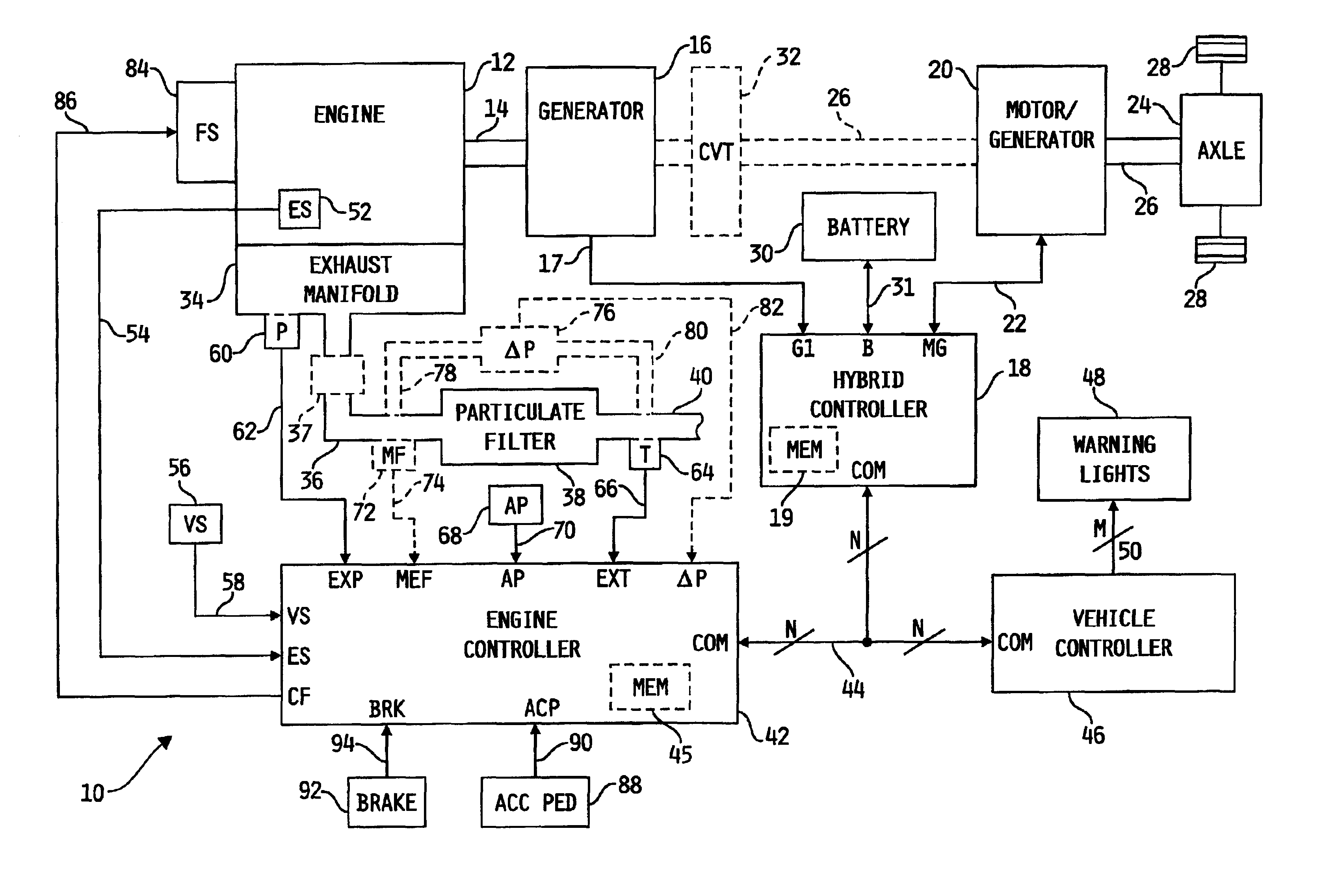
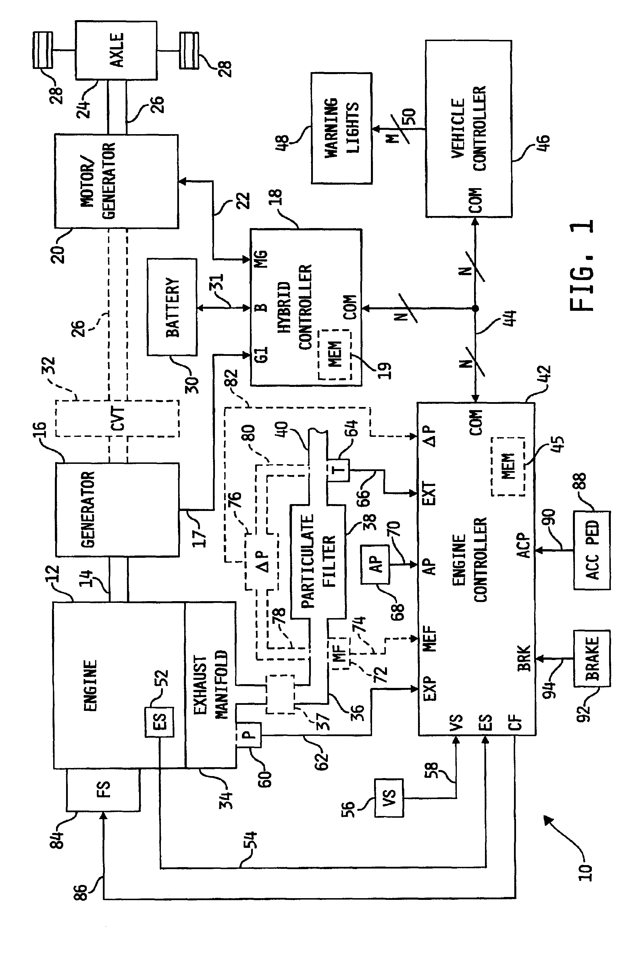
[0036]Referring now to FIG. 1, one preferred embodiment of a system 10 for controlling particulate filter temperature in a hybrid-engine electric vehicle application, in accordance with the present invention, as shown. System 10 includes an internal combustion engine 12 coupled to a generator 16 via drive shaft 14. Generator 16 may be of known construction and is responsive to rotation of...


PUM


Abstract

A system for controlling the temperature of a particulate filter coupled to an exhaust outlet of an internal combustion engine includes a controller responsive to volumetric flow and temperature of exhaust gas to determine a filter regeneration parameter. In a hybrid electric-engine vehicle application, various control strategies are implemented as a function of the regeneration parameter to control exhaust gas temperature suitably for proper regeneration of the particulate filter. Such strategies include shifting the duty cycle of the engine toward lower engine speed operation along lines of constant power output, modifying the ratio of electrical power and engine power and controlling recharging of the battery supplying electrical energy to the vehicle's electric drive motor under vehicle deceleration conditions. In vehicle applications including a transmission coupled directly to the engine, shift points of the transmission are modified as a function of the regeneration parameter to control exhaust gas temperature.

Description

FIELD OF THE INVENTION[0001]The present invention relates generally to controlling the temperature of a particulate filter disposed within a stream of exhaust gas produced by an internal combustion engine, and more specifically to such applications wherein the particulate filter temperature is controlled in a manner that encourages frequent and / or complete regeneration thereof.BACKGROUND OF THE INVENTION[0002]Allowable limits of particulates and noxious gases produced by internal combustion engines, including those produced by diesel engines, are generally regulated by the Environmental Protection Agency (EPA). Manufacturers of such engines have accordingly devised techniques for controlling exhaust emissions, and with regard to particulate emissions many now include within the exhaust system a particulate filter or trap, sometimes referred to as a soot filter. Particulate filters are generally designed to collect particulate emissions within the exhaust stream and either continuous...

Claims


Application Information

Patent Timeline
Patent Type & Authority Patents(United States)
IPC IPC(8): B01D46/44B01D53/22B60K6/04B60K6/00F01N3/023F01N9/00F02D41/02F01N11/00F02B37/00B60K6/442B60K6/46B60K6/48B60K6/54B60K6/543B60W10/06B60W10/08B60W10/10B60W20/00
CPCF01N3/023F01N9/005F01N9/007F01N11/002F01N11/005F02D41/0235F02D41/029F02D41/1445F02D41/1448B01D46/444B01D46/446B01D46/448B01D53/228B60K6/442B60K6/46B60K6/48B60K6/54B60K6/543B60W10/06B60W10/08B60W10/10B60W20/00F01N9/002B60Y2300/476F01N2430/00F01N2430/06F01N2550/04F02B37/00F02D2041/026F02D2041/0265F02D2200/0802F02D2200/503F16H2300/14Y02T10/54Y02T10/6217Y02T10/6221Y02T10/6234Y02T10/6286B01D2279/30B60L2240/445B60W2510/068Y02T10/47Y10S903/945Y10S903/917Y10S903/918B60L3/0023B60L15/2054B60L2240/12B60L2240/36B60L2240/421B60L2240/423B60L2240/441B60L2240/443B60L2240/486B60L2250/10B60L2250/16B60L2250/26B60L2270/12B60W2050/143B60L50/16B60L50/61Y02T10/40Y02T10/62Y02T10/64Y02T10/70Y02T10/7072Y02T10/72B60W20/15
Inventor BUNTING, BRUCE G.MILLER, PAUL R.STOIA, BRADLEE J.SURESH, S. ARVINDRADOVANOVIC, ROD
Owner CUMMINS INC
Why Eureka
Try Eureka