Journal turning lathe having dual feed screw drive

a screw drive and journal technology, applied in the direction of portable lathes, metal-working machine components, manufacturing tools, etc., can solve the problems of some tolerance problems in the lathe described in my '378 patent, and achieve the effect of being easily adjusted

Inactive Publication Date: 2005-06-07
HYDRATIGHT OPERATIONS INC
View PDF6 Cites 15 Cited by
  • Summary
  • Abstract
  • Description
  • Claims
  • Application Information

AI Technical Summary

Problems solved by technology

As such, the lathe described in my '378 patent had some tolerance problems when doing large shafts.

Method used


Image

  • Journal turning lathe having dual feed screw drive
  • Journal turning lathe having dual feed screw drive
  • Journal turning lathe having dual feed screw drive

Examples


Embodiment Construction

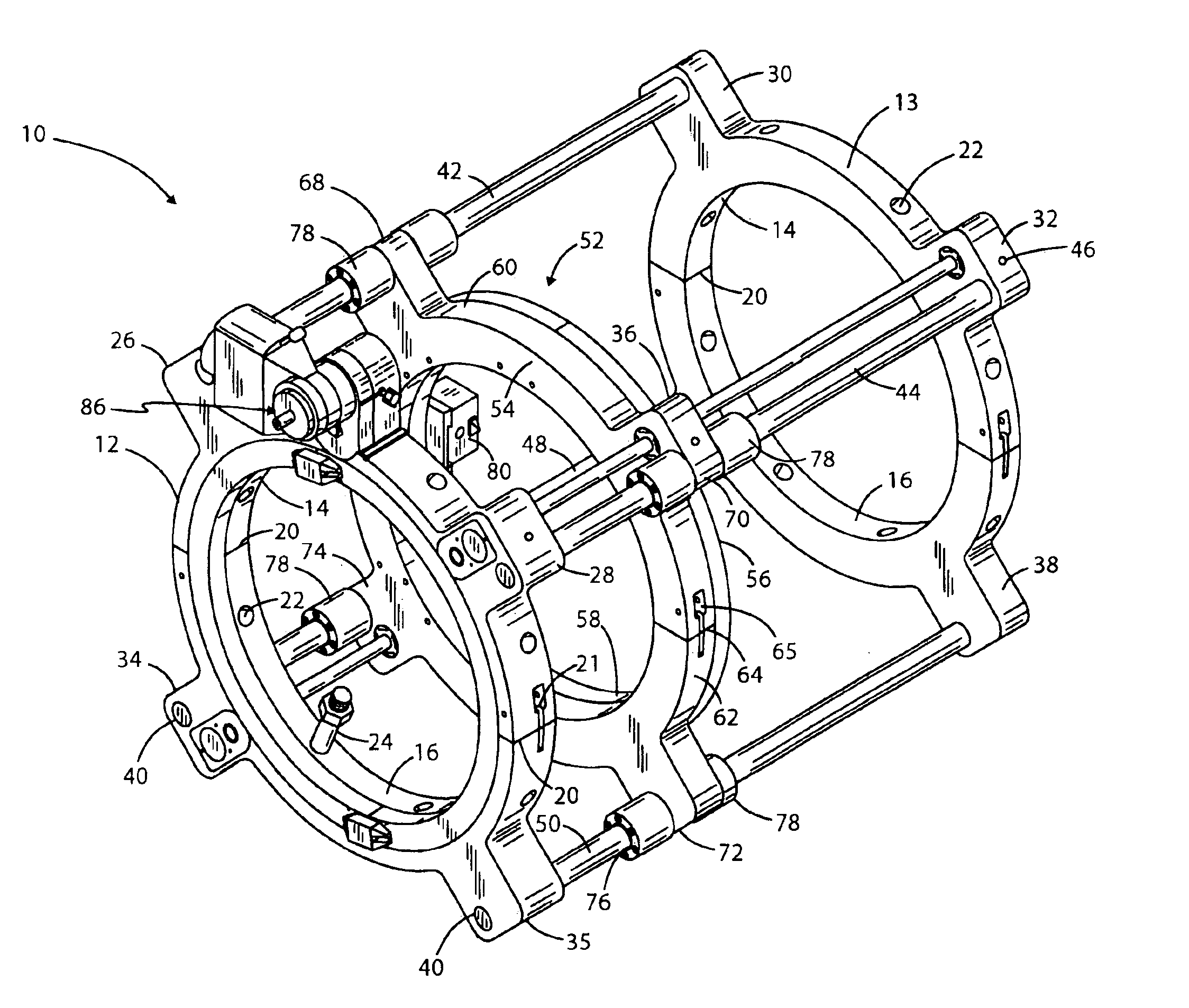
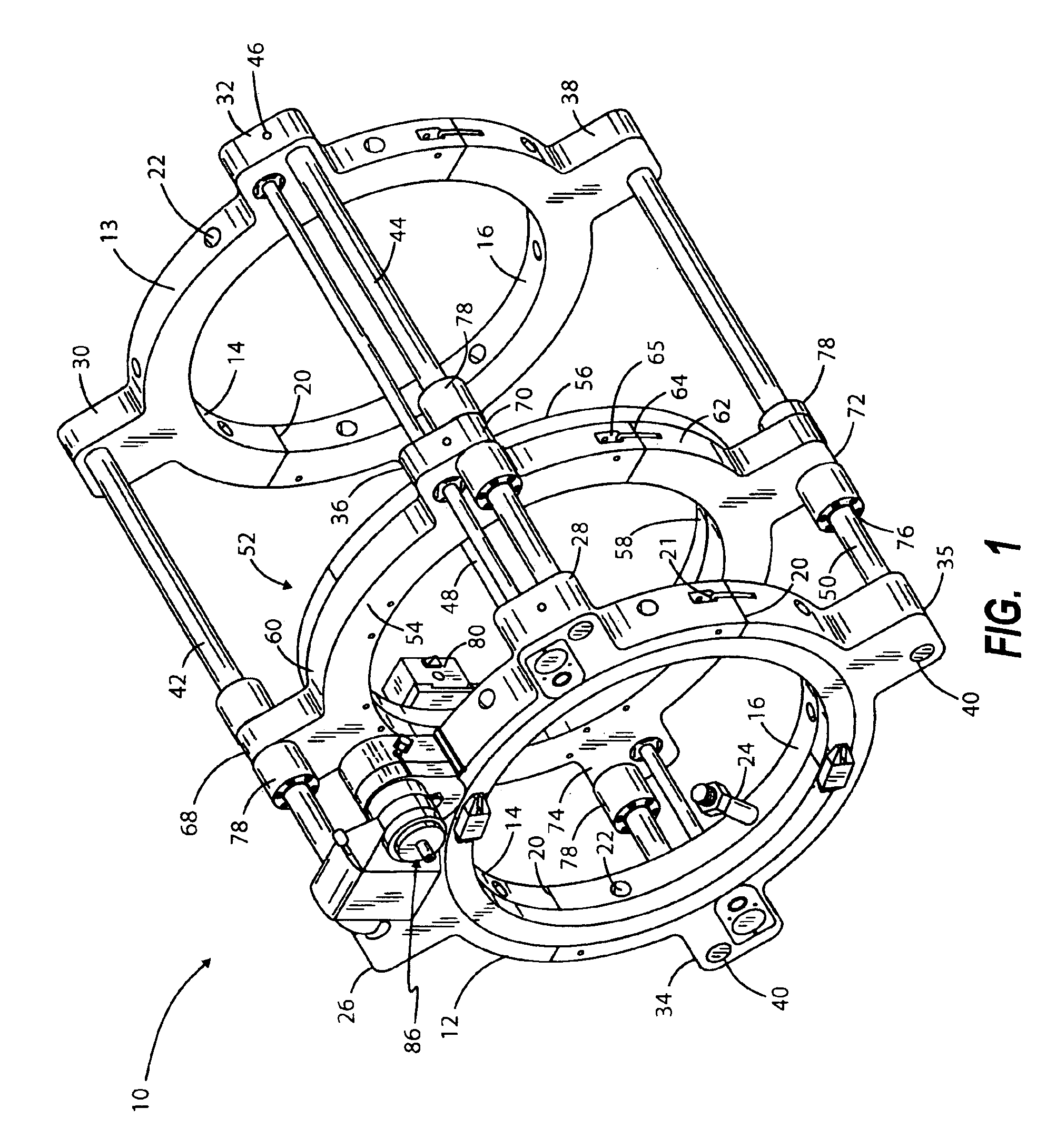
[0013]Referring first to FIG. 1, there is indicated generally by 10 a portable journal turning lathe constructed in accordance with the present invention. It is adapted to be mounted on a shaft or pipe (not shown) whose surface is in need of machining. The journal turning lathe 10 is seen to comprise a first and second clamping rings 12 and 13 having an inside diameter large enough to surround the workpiece to be machined. Clamping ring 12 and clamping ring 13 have substantially the same shape and size. Each includes semi-circular segments 14 and 16 which can be releasably fastened together along a parting line 20 by swing bolts 21 to form an annulus.

[0014]Threaded bores 22 are radially formed through the thickness dimension of the clamping rings. A plurality of centering bolts 24 are threadedly fitted into the threaded bores 22. The centering bolts 24 are moved in and out of the threaded bores 22 in a radial direction to accommodate a range of workpiece sizes that are to be machine...


PUM

PropertyMeasurementUnit
forcesaaaaaaaaaa
speedaaaaaaaaaa
radial displacementaaaaaaaaaa

Abstract

A portable journal turning lathe for machining a shaft at a job site, including a pair of clamping rings that are adapted to be centered at spaced apart locations along the length of the shaft to be machined. Extending between the clamping rings is a plurality of guide shafts which slidingly support a split ring clamshell assembly. A cutting tool carrier is affixed to the rotatable ring portion of the clamshell assembly so that when the movable ring is driven the tool carrier orbits the shaft being machined. A plurality of feed screws driven by a servomotor translates the clamshell assembly along the guide shafts.

Description

BACKGROUND OF THE INVENTION[0001]I. Field of the Invention[0002]This invention relates generally to apparatus for repairing and refurbishing the bearing surfaces of rotating shafts of large machines at a job site, and more particularly to a portable journal turning lathe that can easily be transported to a location in the field where a machine is to be repaired, mounted in place on the machine's shaft to be turned and then operated to remove any scoring and other surface irregularities from the shaft so that it is ready for replacement of its bearings.[0003]II. Background of the Invention[0004]In my earlier U.S. Pat. No. 6,065,378 I describe a portable journal turning lathe including a pair of clamping rings that are adapted to be centered at spaced-apart locations along a length of a shaft to be refurbished. Extending between the clamping rings is a plurality of guide shafts which slidingly support a split-ring clamshell assembly. A cutting tool carrier is affixed to the rotatable ...

Claims


Application Information

Patent Timeline
Patent Type & Authority Patents(United States)
IPC IPC(8): B23Q5/40B23Q5/22B23Q9/00B23B3/00B23B5/08B23B3/26B23Q1/00B23Q1/01
CPCB23B3/26B23B5/08B23Q1/017Y10T82/25Y10T82/2549Y10T82/22Y10T82/2527Y10T82/2522B23Q9/00
Inventor RICCI, DONATO L.
Owner HYDRATIGHT OPERATIONS INC
Why Eureka
Try Eureka