
Hydropneumatic accumulator

Inactive Publication Date: 2005-06-07
HYDAC TECH GMBH
View PDF10 Cites 16 Cited by
  • Summary
  • Abstract
  • Description
  • Claims
  • Application Information

AI Technical Summary

Benefits of technology

[0006]Objects of the present invention are to provide an accumulator characterized by especially good operating behavior of the membrane so that a long service life can be achieved, even during operation with high pressure ratios and high rates of pressure change.
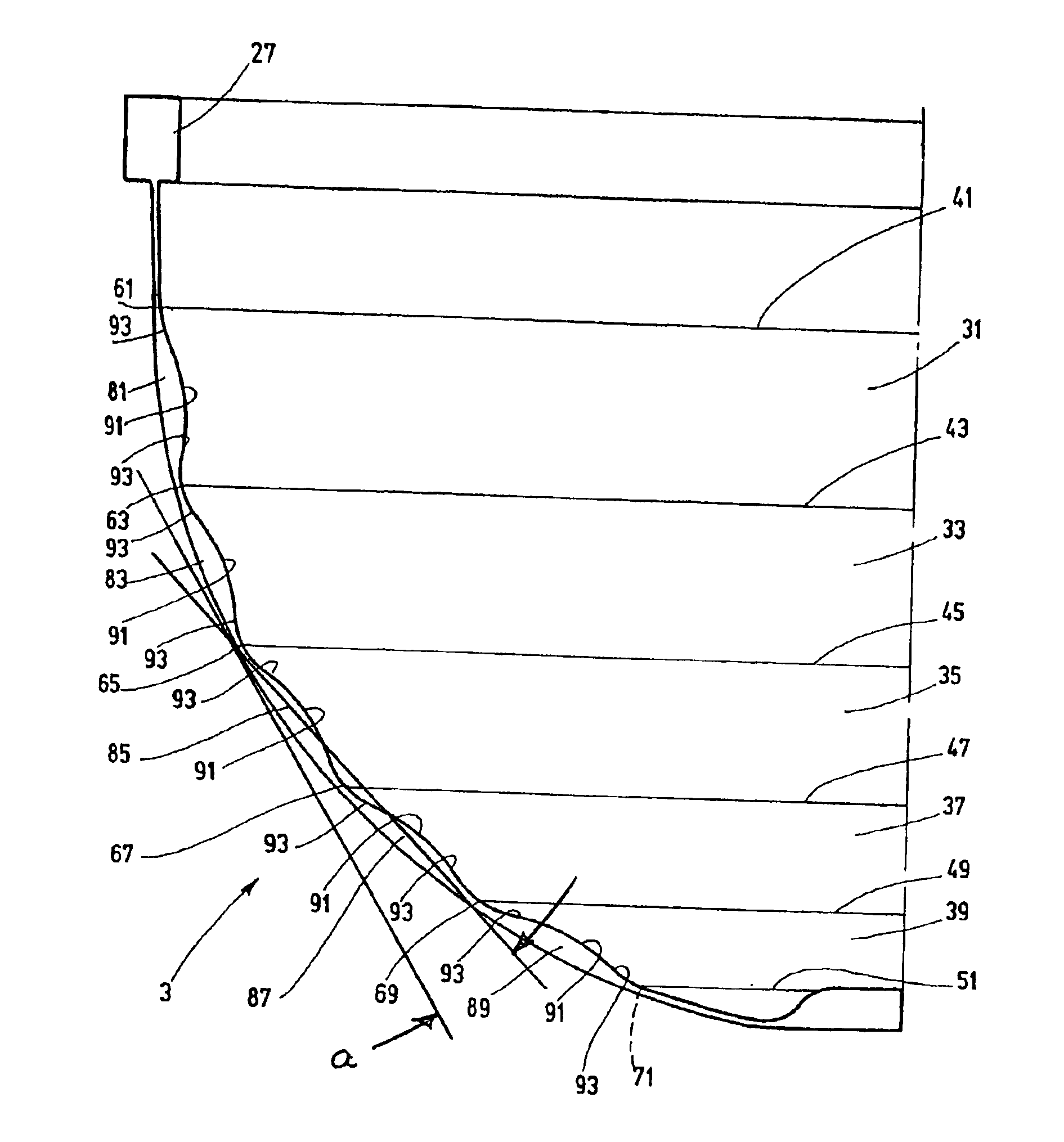
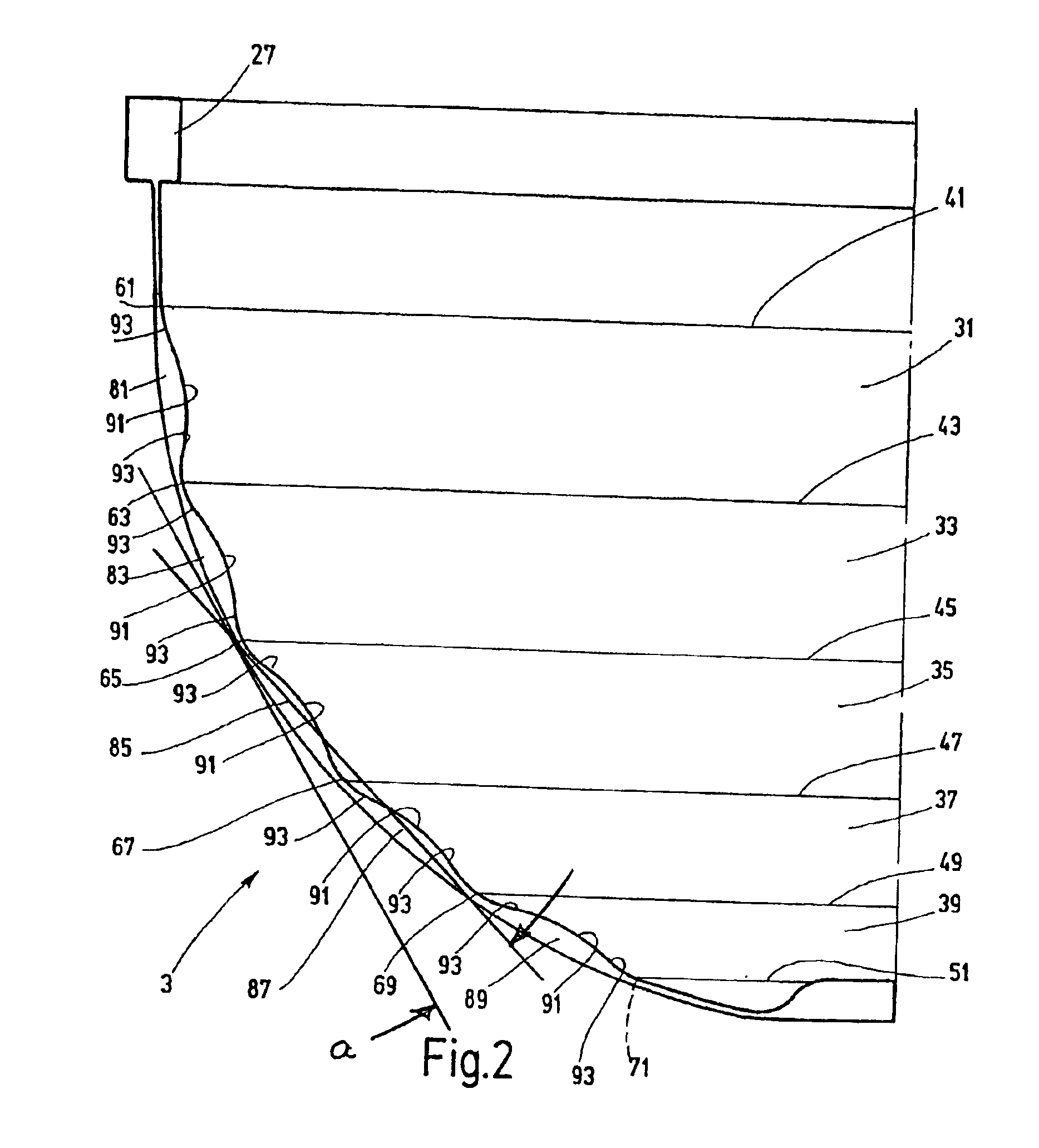
[0008]The shape of the present invention has the areas of the membrane which taper off flatly towards the articulations, and avoids the danger that when the membrane folds of overly sharp kinks at the joints form, as in the aforementioned, known generic accumulators. Thus the damaging notch effect is prevented. Conversely, the articulated movements for the shape of the present invention take place with a certain radius of curvature, by which the danger of local overstress of the membrane is prevented. Without overly enlarging the wall thickness of the membrane, thus, comparatively large pressure amplitudes and rates of pressure change are allowable.
[0010]In one preferred embodiment of the accumulator of the present invention, the weak points have a concave shape. The membrane has an alternating sequence of convex with concave areas. This arrangement yields especially good bending and unrolling properties in the folding of the membrane. Preferably, the membrane, in its initial position along its outer surface, has a permanent and essentially uniform curvature, and the membrane is designed in the manner of a hemisphere in its initial position.
[0014]The present invention makes it advantageously possible to produce the membrane from a gas-tight monolayer plastic, for example from a polyamide, a polyamide blend, polyethylene terephthalate, polyethylene naphthalate or polyvinylidene chloride.

Problems solved by technology

Moreover, the beads in the areas adjacent to one another have a steeply tapering shape so that a careful unwinding process cannot be achieved with this known membrane.

Method used


Image

  • Hydropneumatic accumulator
  • Hydropneumatic accumulator
  • Hydropneumatic accumulator

Examples


Embodiment Construction

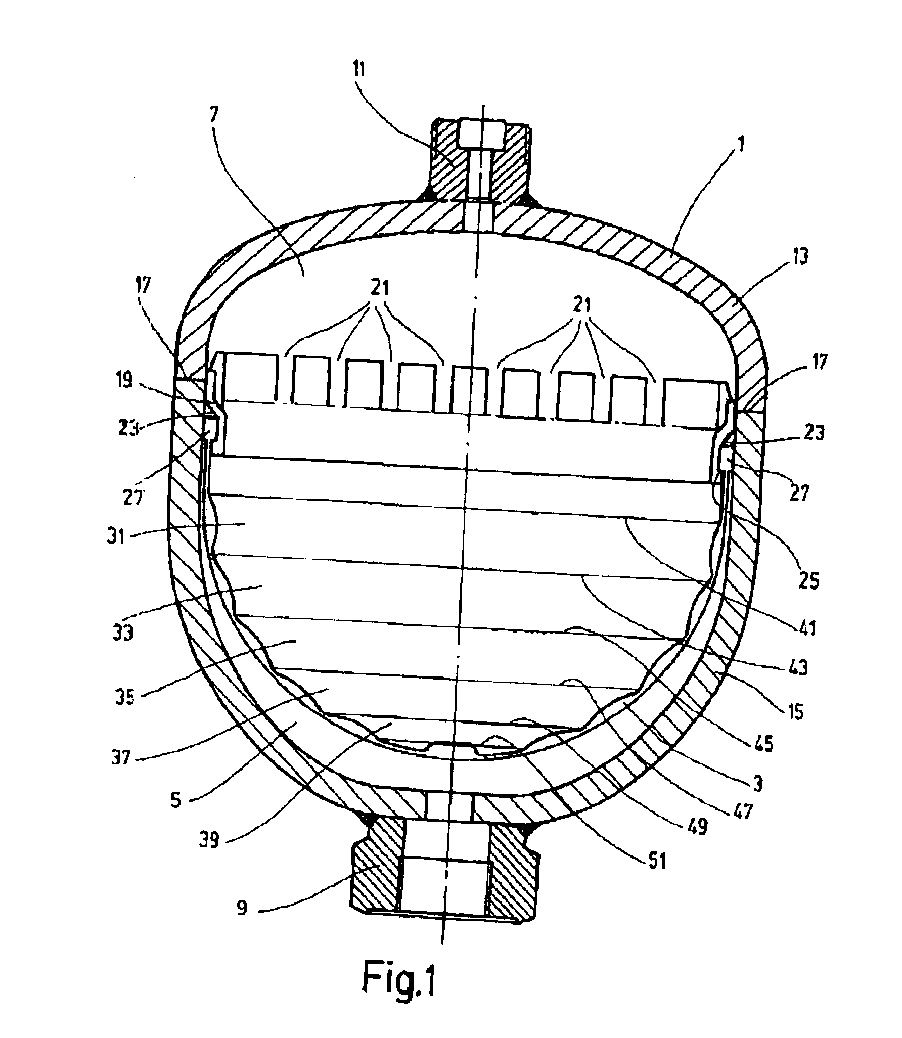
[0021]The accumulator shown in FIG. 1 is a so-called membrane accumulator with a separating element located in the housing 1 and being in the form of a membrane 3. The membrane 3 separates the interior of the housing 1 into a first chamber, in this example a liquid chamber 5, and into a second chamber, in this example a gas chamber 7. Both the liquid chamber 5 and the gas chamber 7 each have a connection 9 and 11, respectively, by which the accumulator can be connected to the pipelines of a hydraulic system (not shown) and by way of which the gas pressure can be set, respectively. Comparable accumulators with the previously described features are state of the art. The accumulator is explained below only to the extent which is necessary for description of the present invention.

[0022]The housing 1 includes, when viewed in FIG. 1, a top housing shell 13 and a bottom housing shell 15 which abut one another along a seam 17. Along this seam 17, the two shells 13 and 15 can be joined to on...


PUM


Abstract

A hydraulic accumulator includes an accumulator housing (1) and a diaphragm (3) forming a displaceable partition element in the housing between a gas chamber (7) and a liquid chamber (5). The membrane has several annular regions (31, 33, 35, 37, 39), interconnected by annular weak points (61, 63, 65, 67, 69, 71). The annular regions (31, 33, 35, 37, 39), have protuberances (81, 83, 85, 87, 89) on the interior face of the membrane (3) facing away from the wall of the accumulator housing (1). The protuberances are at their thickest in the central region between adjacent weak points, thus increasing the wall thickness of the membrane (3), and are at least partially convex (91,93), tapering off to a respective flat form towards the weak points.

Description

FIELD OF THE INVENTION[0001]The present invention relates to a hydropneumatic accumulator with an accumulator housing and a membrane. The membrane is located in the housing and forms a movable separating element between a first chamber, especially a gas chamber, and a second chamber, especially a liquid chamber. Several annular areas of the membrane are interconnected by annular weak points acting as articulations. The annular areas have elevations on the inner side of the membrane facing away from the wall of the accumulator housing.BACKGROUND OF THE INVENTION[0002]Hydropneumatic accumulators are known in a host of constructions and embodiments. One of the main tasks of hydropneumatic accumulators (accumulators) is to accommodate certain volumes of pressurized liquid of a hydraulic system and to return it if necessary to the system.[0003]DE-A-41 31 790 discloses a bladder or membrane for an accumulator comprising an elastic material layer. The elastic material layer is laminated wi...

Claims


Application Information

Patent Timeline
IPC IPC(8): F15B1/00F15B1/10F15B1/14F15B1/08
CPCF15B1/10F15B1/14F15B2201/205F15B2201/415F15B2201/3156F15B2201/41F15B2201/3151
Inventor BALTES, HERBERTLEHNERT, MARKUS
Owner HYDAC TECH GMBH
Learn More