Seal device for tubular member

a tubular member and sealing device technology, applied in the direction of hose connection, cable termination, mechanical apparatus, etc., can solve the problems of increasing weight, difficult to fabricate an elongated tube having a conventional tube folding structure, and the inability to insert the etc., to achieve excellent workability in inserting the seal tube into the fluid passag

Inactive Publication Date: 2005-06-07
BRIDGESTONE CORP
View PDF20 Cites 17 Cited by
  • Summary
  • Abstract
  • Description
  • Claims
  • Application Information

AI Technical Summary

Benefits of technology

[0007]In view of the above-described problems observed in the prior art, an object of the present invention is to provide a seal device for a tubular member or the like, by which a portion to be sealed can be sufficiently sealed even under a high pressure, and which can be used even in a curved passage, is light in weight, and can be easily handled.
[0013]At this time, since the vicinity of the center of each of the plurality of seal tubes constituting the connected-tube body is press-fitted to the inner surface of the fluid passage such as a tubular member at a maximum pressure corresponding to an inner pressure, press-fitting force acting on the inner surface of the fluid passage such as a tubular member can be increased by the connected-tube body as a whole, and further, an area of a portion press-fitted to the inner surface of the fluid passage such as a tubular member at the maximum pressure can be increased in comparison with the case where only one seal tube is expanded inside of the fluid passage such as a tubular member so as to seal the inside of the fluid passage such as a tubular member. Consequently, it is possible to seal the inside of the fluid passage such as a tubular member against a high pressure, and further, to enhance a sealing property with respect to the fluid passage such as a tubular member.
[0014]Moreover, even if the fluid passage such as a tubular member is curved or bent, the connected-tube body can be easily curved or bent along the fluid passage such as a tubular member. Therefore, the plurality of seal tubes can be readily inserted into the curved or bent fluid passage such as a tubular member and a sealing property with respect to the curved or bent fluid passage such as a tubular member can be enhanced.
[0017]At this time, since the vicinity of the center of each of the plurality of seal tubes is press-fitted to the inner surface of the fluid passage such as a tubular member at a maximum pressure corresponding to an inner pressure if the plurality of seal tubes are simultaneously expanded inside of the fluid passage such as a tubular member, press-fitting force acting on the inner surface of the fluid passage such as a tubular member can be increased by the connected-tube body as a whole, and further, an area of a portion press-fitted to the inner surface of the fluid passage such as a tubular member at the maximum pressure can be increased in comparison with the case where only one seal tube is expanded inside of the fluid passage such as a tubular member so as to seal the inside of the fluid passage such as a tubular member. Consequently, it is possible to seal the inside of the fluid passage such as a tubular member against a high pressure, and further, to enhance a sealing property with respect to the fluid passage such as a tubular member.
[0018]Moreover, even if the fluid passage such as a tubular member is curved or bent, the connected-tube body can be easily curved or bent along the fluid passage such as a tubular member. Therefore, the seal tube can be readily inserted into the curved or bent fluid passage such as a tubular member and a sealing property with respect to the curved or bent fluid passage of the tubular member can be enhanced.
[0024]As described above, by using the seal device for a tubular member or the like according to the invention, secure sealing can be achieved even if the inside pressure of the fluid passage such as a tubular member, at a portion to be sealed, is high, and further, the workability in inserting the seal tube into the fluid passage is excellent with secure sealing even if the fluid passage is curved.

Problems solved by technology

However, in the case where the passage or the hole is curved, if the curvature is large, the tube cannot be inserted since the base member is rigid and has a predetermined length.
Moreover, although it is advantageous to use a long tube or a plurality of tubes connected to each other for a passage such as a tubular member at an inlet or an outlet, in the case where the pressure inside of the container or equipment is high, it is difficult to fabricate an elongated tube having a conventional tube folding structure, and further, the folded portion makes a diameter large.
Additionally, the base member also must be elongated, thereby resulting in an increase in weight, and the base member cannot be used in the case where the passage is curved.

Method used


Image

  • Seal device for tubular member
  • Seal device for tubular member
  • Seal device for tubular member

Examples


first embodiment

(First Embodiment)

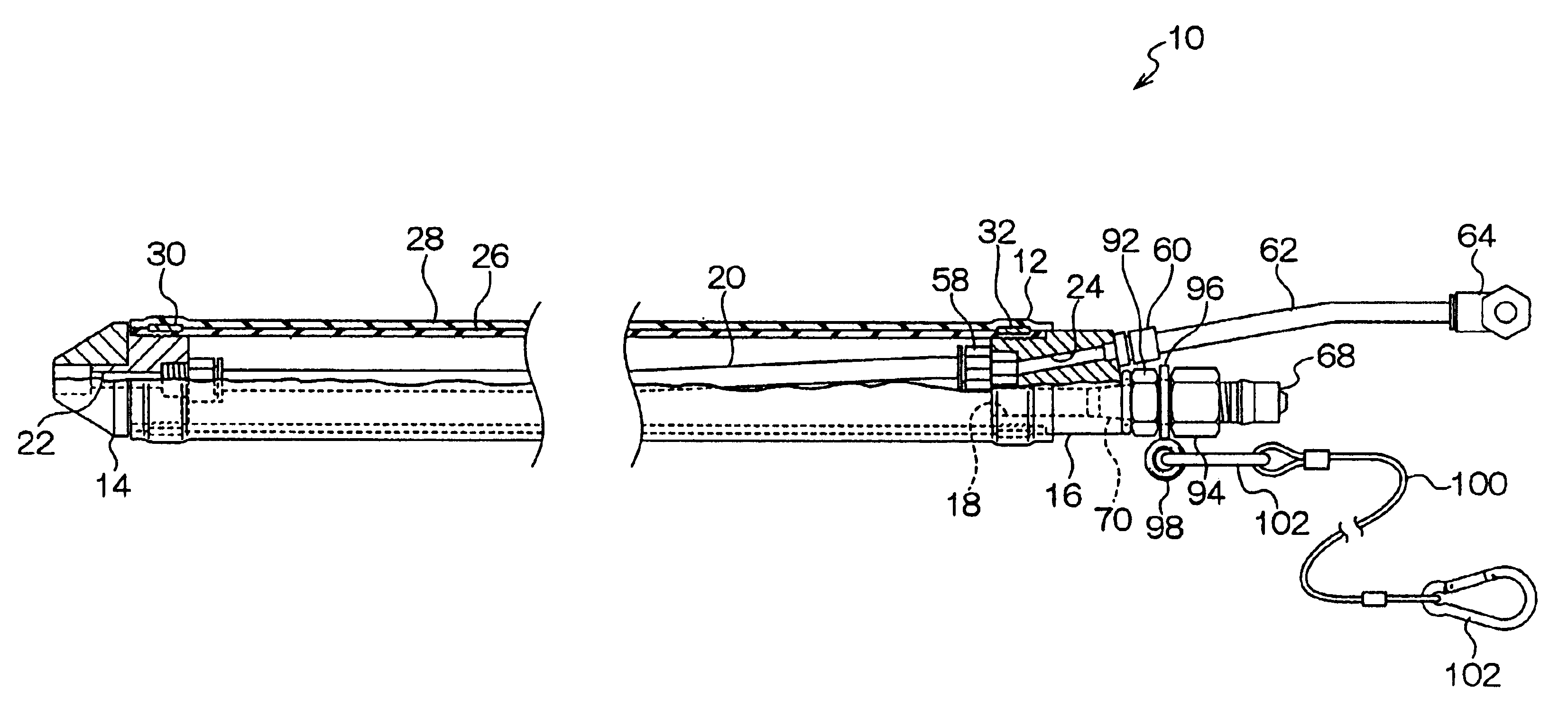
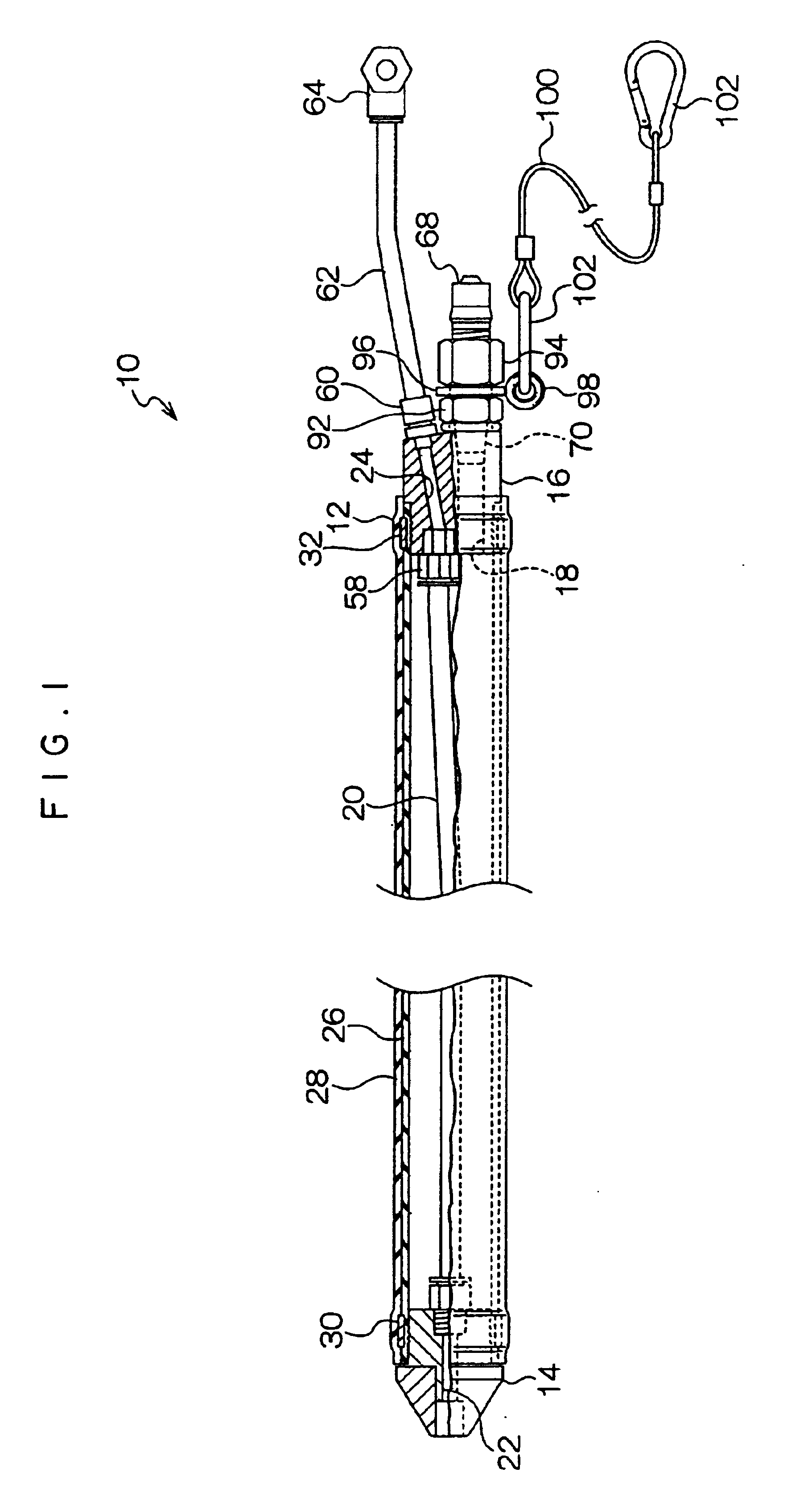
[0036]FIG. 1 shows a seal device for a tubular member or the like (hereinafter simply referred to as “a seal device”) in a first embodiment of the invention. A seal device 10 is formed into a relatively long and cylindrical shape, and is provided with a cylindrical seal tube 12 opened at both ends thereof (i.e., a fore end and a rear end) along a longitudinal direction. At the fore end of the seal tube 12 is securely inserted a base member 14; in contrast, at the rear end of the seal tube 12 is securely inserted another base member 16. Consequently, both ends of the seal tube 12 are dosed by the base members 14 and 16, so that the inside of the seal tube 12 is turned into a tightly sealed state. At the base member 16, a fluid injection passage 18 is formed in such a manner as to penetrate along the longitudinal direction of the seal tube 12. The fluid injection passage 18 is adapted to inject a fluid such as gaseous nitrogen into the seal tube 12, so as to expand t...

second embodiment

(Second Embodiment)

[0050]FIG. 6 shows a seal device in a second embodiment of the invention. Here, constituent elements having the same configuration and function in the seal device in the second embodiment of the invention as those in the seal device 10 in the first embodiment are designated at the same reference numerals, and therefore, their explanations will be omitted below.

[0051]A seal device 110 in the present embodiment is provided with two seal tubes 112 and 114 and a connecting base member 116 for connecting these seal tubes 112 and 114 to each other. Here, each of the seal tubes 112 and 114 basically has the same configuration as that of the seal tube 12 in the first embodiment. The connecting base member 116 is formed into a substantially columnar shape, as shown in FIG. 8, and a ring-like flange 118 extending toward the outer periphery is integrally formed at the intermediate portion thereof in an axial direction. In the connecting base member 116, there are provided in...


PUM


Abstract

A seal device is constituted of a plurality of seal tubes. After a connected-tube body having base members disposed at a fore end and a rear end is inserted into a fluid passage such as a tubular member, the seal tubes are expanded by injecting gaseous nitrogen into each of the seal tubes. The intermediate portions of the seal tubes along a longitudinal direction are press-fitted to the inner surface of the fluid passage over the entire circumference thereof, whereby the fluid passage is sealed. Since the connected-tube body is easily bent in the vicinity of a connecting base member between the tubes, the connected-tube body can be easily curved along the fluid passage, thus facilitating an operation for inserting the connected-tube body into the fluid passage and also enhancing a sealing property with respect to the fluid passage.

Description

CROSS-REFERENCE TO RELATED APPLICATIONS[0001]This application claims priority under 35 USC 119 from Japanese Patent Applications No. 2002-362664 and No. 2003-386149, the disclosures of which are incorporated by reference herein.BACKGROUND OF THE INVENTION[0002]1. Field of the Invention[0003]The present invention relates to a seal device for a tubular member or the like, for sealing a passage such as a tubular member at an inlet or an outlet in various containers or equipment by the use of an expanded tube.[0004]2. Description of the Related Art[0005]A device for gripping a bottle or the like, wherein a conventional rubber tube is expanded by injecting a fluid such as air into the tube, thereby sealing a mouth of the bottle or the like, is known. One example of such a device is disclosed on pages 4 to 5 and FIG. 1 of Japanese Patent Application Publication (JP-B) No. 7-29266. In the conventional device, both ends of a tube, into which a fluid can be injected, are respectively fixed a...

Claims


Application Information

Patent Timeline
Patent Type & Authority Patents(United States)
IPC IPC(8): F16L55/134F16L55/10B65B39/00B65B39/02F16J15/46
CPCF16L55/134
Inventor ONUKI, GIICHINISHIMURA, HIROHITO
Owner BRIDGESTONE CORP
Why Eureka
Try Eureka