Electromechanical locking method and device

a technology of electromechanical and locking method, applied in the field of electromechanical locking method and device, electromechanical devices, etc., can solve the problems of increasing the size of the electromagnet, increasing the cost of the magnet as well as power consumption, and not being able to easily open the door by people,

Inactive Publication Date: 2005-06-07
SMITH JERRY R
View PDF17 Cites 49 Cited by
  • Summary
  • Abstract
  • Description
  • Claims
  • Application Information

AI Technical Summary

Benefits of technology

[0006]It is an object of the present invention to provide a new and useful electromagnetic lock that may be used to secured tw...

Problems solved by technology

The electromagnet is of such strength that a person may not readily open the door when the electromagnet is activated due to the strength of the magnetic attraction of the electromagnet for the armature.
This naturally increases the cost of the magnet as w...

Method used


Image

  • Electromechanical locking method and device
  • Electromechanical locking method and device
  • Electromechanical locking method and device

Examples


first embodiment

[0050]A representative latch element for this first embodiment of the present invention is depicted in FIGS. 7 and 8. Here, latch element 60 is in the form of a pawl having a base 62 and an elongated arm 64 that terminates in a hook 66. A pair of oppositely projecting trunnions 68 are cylindrical in configuration and extend oppositely outwardly from base 62. Arm 64 is provided with a post 65 on one side thereof and an inclined plane 69 forms a cam surface, the purpose of which is described in greater detail below.

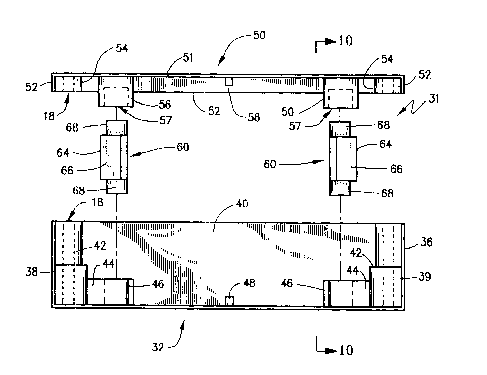
[0051]With reference now to FIG. 9, the assembly of base 32 and cover 50 to form housing 31 along with the mounting of a pair of latch elements 60 is shown. As may be seen in FIG. 9, when cover 50 is placed on base 32, blocks 54 will abut blocks 42 with bores 18 being aligned. It may be here noted that blocks 42 may be tiered, for dimensional reasons, if desired. Each of seats 46 are opposed to a respective seat 56 to form a seat pair for mounting trunnions 68 of each latch...

third embodiment

[0062]the present invention is shown in FIG. 21. Here, it may be seen that the electromagnet 225 is formed as part of the catch piece 290. Head portion 294 provides a pair of lips 296, and it could be understood that catch piece 290 can be formed of a core material for the electromagnetic coils that form electromagnet 225. In any event, latching assembly 220 includes an arming member 223 that is slideably mounted on posts 228 and biased by springs 282 as shown in FIG. 21. Latching elements 260 are pivotally mounted at opposite ends of plate 224 on axles 261 and, when contacted by catch piece 290 are held in the release position (shown in FIG. 21) by means of suitable cam surfaces. Coil springs (not shown but similar to those described below in FIGS. 22 and 23) extend around axles 262 to bias latching members 260 into the capture position. However, due to the action of springs 282, arming member 223 forces cam members 260 into the release position, as described above. When current is...

fourth embodiment

[0063]Finally, turning to FIGS. 22 and 23, the present invention is shown. Here, latch assembly 320 is in the form of a plate 24 that is mounted to a first structure 314 by means of a bolt 322 that has a base block 340 received in a cavity 342 formed therein. A spring 382 biases plate 320 into the first position adjacent structure 314. Catch 390 is mounted to a second structure 312 and comes into abutment with plate 324 when in a received position in latch assembly 320. Plate 324 has associated therewith an electromagnet 325, and a pair of latch elements 360 are rotatably journaled on axles 361 and are biased into the capture state by means of coil springs 384.

[0064]As is shown in FIG. 23, when current is supplied to electromagnet 325, catch piece 390 is magnetically attracted to plate 324. Movement of catch piece 390 away from structural piece 314 moves plate 324 away from piece 314 against the force of compression spring 382. When this occurs, springs 384 act to rotate latch eleme...


PUM


Abstract

An electromechanical lock includes a latching assembly secured to a first structure, a catch piece secured to a second structure, and an electromechanical device. The latching assembly includes at least one latch element movable between a capture and release states to mechanically engage and disengage the catch piece, an arming member movable between a first and second positions wherein the latch element is released and captured, and a biasing element to urge the arming member into the first position. When the electromagnetic device is switched “on”, it magnetically engages the arming member with sufficient force to overcome the biasing force whereby movement of the catch piece away from the received state results in the latch element moving into the capture state to prevent separation of the first and second structures; when the electromagnetic device is switched “off”, the first and second structures may be separated.

Description

FIELD OF THE INVENTION[0001]The present invention broadly concerns locking methods and systems. More particularly, the present invention is directed to electromechanical devices that may be employed to secure two structures together which may otherwise move relatively apart from one another. The present invention is also directed to a method of a electromechanically locking two structures together. This invention is especially adapted for use in electromechanically locking a door.BACKGROUND OF THE INVENTION[0002]The ability to lockably secure two structures together to permit or prevent relative movement therebetween has been a goal of many locking systems. A plethora of different locking mechanisms have been developed over the course of history. These include key actuated locks, combination locks, code activated locks and the like.[0003]Many types of locks are associated with doors in order to selectively lock a door in a closed position. Authorized personnel are provided with a ke...

Claims


Application Information

Patent Timeline
IPC IPC(8): E05C19/00E05C19/16
CPCE05C19/166Y10T292/11Y10T292/699
Inventor SMITH, JERRY R.
Owner SMITH JERRY R
Why Eureka
Try Eureka