High dynamic range integrated receiver

a receiver and dynamic range technology, applied in the direction of photometry using electric radiation detectors, optical radiation measurement, instruments, etc., can solve the problems of increasing packaging size and cost, packaging complexity, size and cost, and dynamic range limitation of optical receivers at low optical input power, so as to simplify the assembly process of hdri rx, reduce size and cost, and facilitate manufacturing

Inactive Publication Date: 2007-10-23
LUMENTUM OPERATIONS LLC
View PDF37 Cites 4 Cited by
  • Summary
  • Abstract
  • Description
  • Claims
  • Application Information

AI Technical Summary

Benefits of technology

[0014]The present invention provides a HDRI Rx packaging solutions of reduced size and cost by combining the beam shaping and the beam redirecting functions into a single optical component. In the preferred solution the beam shaping and the beam-redirecting functions are integrated into a single optical component that can be easily fabricated, e.g. by plastic injection molding. Employment of a single optical component with fixed relation between the beam shaping and the beam redirecting optical surfaces significantly simplifies the HDRI Rx assembly process, in particular when the VOA structures and the photo-detector device are positioned adjacent one another on the same support structure.
[0015]The molded component may also combine mechanical mounting features and the above optical functions leading to simplified assembly process and further reduction in packaging complexity and production cost.
[0016]In another embodiment the dual-mirror arrangement is used to redirect the light reflected from the MEMS actuator towards the PD photosensitive area, reducing assembly sensitivity to angular misalignments.

Problems solved by technology

The dynamic range of an optical receiver is limited at low optical input powers by the coupling loss and photo-detector sensitivity.
Integration of a reflective MEMS actuator into a receiver package requires the addition of optical components leading to an increase in packaging complexity, size and cost, as illustrated in FIG. 3. FIG. 3 presents a conventional optical layout of an HDRI Rx employing a reflective actuator 303 working on a collimated beam.
The focusing lens 305 contributes to an increase in packaging size and alignment complexity.
Integration of a reflective MEMS structure (as the VOA actuator 303) into the HDRI Rx comes with increased packaging size, complexity and cost.

Method used


Image

  • High dynamic range integrated receiver
  • High dynamic range integrated receiver
  • High dynamic range integrated receiver

Examples


first embodiment

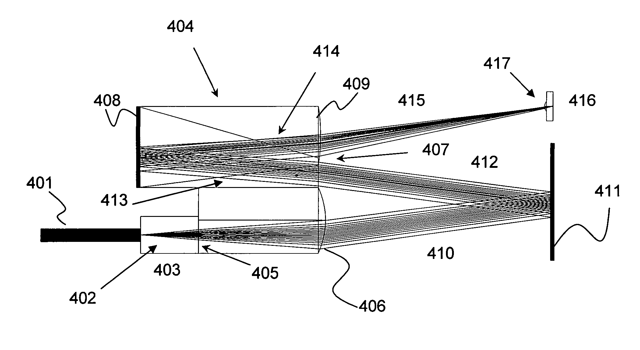
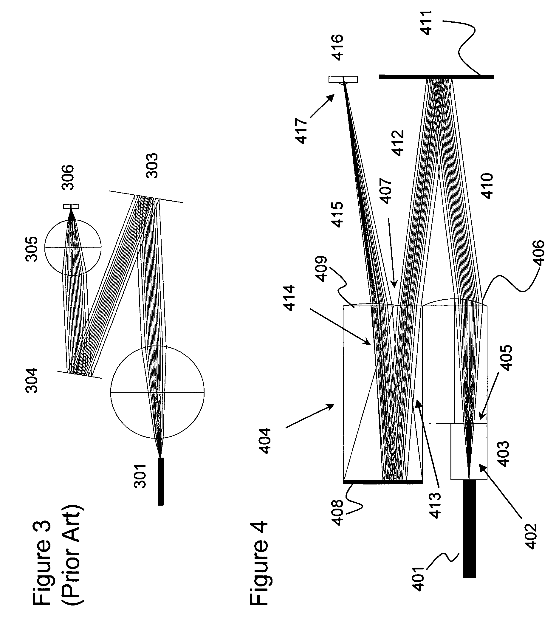
[0030]FIG. 4 illustrates an inline optical layout of an High Dynamic Range Integrated (HDRI) receiver employing a reflective variable optical attenuator (VOA) actuator 411 in accordance with the present invention. A diverging beam 402 launched from an input fiber 401, defining an input port, propagates through a silica block 403 placed in optical contact with the end-face of input fiber 401, and enters the monolithic optical block 404 through an input port defined by a first input planar surface 405, which is also in optical contact with the silica block 403. The silica block 403 has an index of refraction in between that of the input fiber 401 and the optical block 404 providing a gradual transition therebetween for minimizing back reflections from interfaces therebetween. The monolithic optical block 404 integrates five optical interfaces including: in the order of the beam propagation, an input planar surface 405, a collimating lens surface 406, a planar refractive surface 407, a...

second embodiment

[0031]FIG. 5 illustrates an inline optical layout of an HDRI receiver employing a reflective VOA actuator 509 in accordance with the present invention. A diverging optical beam 502 launched from an input fiber 501 propagates through a silica block 503, placed in optical contact with an end-face of the fiber 501, and enters a monolithic optical block 504 through an input port in the form of a first input planar surface 505, which is also in optical contact with the silica block 503. The monolithic optical block 504 integrates four optical interfaces including: in order of beam propagation, an input planar surface 505, a coupling lens surface 506, a planar refractive surface 507, and a planar reflective surface 508. The diverging beam 502 is refracted by the lens surface 506 forming a converging beam 510, which is directed towards the reflective VOA actuator 509 forming a reflected beam 511, i.e. an attenuated beam that includes at least a portion of the converging beam 510. The refle...

third embodiment

[0032]FIG. 6 illustrates an inline optical layout of an HDRI receiver employing a reflective VOA actuator 612 in accordance with the present invention. A diverging beam 602, launched from an input fiber 601, propagates through a silica block 603, placed in optical contact with an end-face of the optical fiber 601, and enters a monolithic optical block 604 through an input port defined by a first input planar surface 605, which is also in optical contact with the silica block 603 for the aforementioned reasons. The monolithic optical block 604 integrates six optical interfaces including in order of beam propagation: the first input planar surface 605, a coupling lens surface 606, a second input planar (refractive) surface 607, first and second planar reflective surfaces 608 and 609, and an output planar refractive surface 610. The diverging beam 602 is refracted by the lens surface 606 forming a converging beam 611, which is directed towards the reflective VOA actuator 612 forming a ...


PUM


Abstract

A high dynamic range integrated (HDRI) receiver includes a variable optical attenuator (VOA) for attenuating an incoming optical signal before the optical signal is directed to a photo-detector for conversion into an electrical signal. An optical block receives the optical signal from an optical fiber and includes optics for directing the optical signal to the VOA, and for directing the optical signal from the VOA to the photo-detector.

Description

CROSS-REFERENCE TO RELATED APPLICATIONS[0001]The present invention is a continuation in part of U.S. patent application Ser. No. 11 / 132,801 filed May 19, 2005 now U.S. Pat. No. 7,068,890, which is a divisional patent application of U.S. patent application Ser. No. 10 / 342,410 filed Jan. 13, 2003 now U.S. Pat. No. 6,954,580, which claims priority from 60 / 360,937 filed Mar. 1, 2002, and the present invention claims priority from U.S. patent application Ser. No. 60 / 714,654 filed Sep. 7, 2005, which are all incorporated herein by reference for all purposes.TECHNICAL FIELD[0002]The present invention relates to optical receivers with extended dynamic range, and in particular to optical receivers with an integrated optical attenuation function to achieve extended operational dynamic range.BACKGROUND OF THE INVENTION[0003]With the growth of optical communication systems there is a continuing demand for lower-cost, high-performance optical components with extended flexibility in operation. Co...

Claims


Application Information

Patent Timeline
Patent Type & Authority Patents(United States)
IPC IPC(8): G02B6/00G02B6/36
CPCG01J1/04G01J1/0407G02B6/4206G01J1/0418G01J1/0204G01J2001/0276G02B6/266
Inventor SOSKIND, YAKOV G.STRUTTMAN, JAMES DOUGLASZACK, JEFFREY
Owner LUMENTUM OPERATIONS LLC
Why Eureka
Try Eureka