Taillight apparatus and method of making

a technology of taillight and apparatus, applied in the field of taillight, can solve the problems of increasing weight and bulky configuration of taillight, and achieve the effect of reducing heat transfer

Inactive Publication Date: 2005-06-07
ILLUME
View PDF31 Cites 74 Cited by
  • Summary
  • Abstract
  • Description
  • Claims
  • Application Information

AI Technical Summary

Benefits of technology

[0012]The material may be supported by a separate enclosure cap that positions the material a spaced distance from the lig

Problems solved by technology

By using multiple lamp bulbs and having several sections to accomplish all the necessary li

Method used


Image

  • Taillight apparatus and method of making
  • Taillight apparatus and method of making
  • Taillight apparatus and method of making

Examples


Embodiment Construction

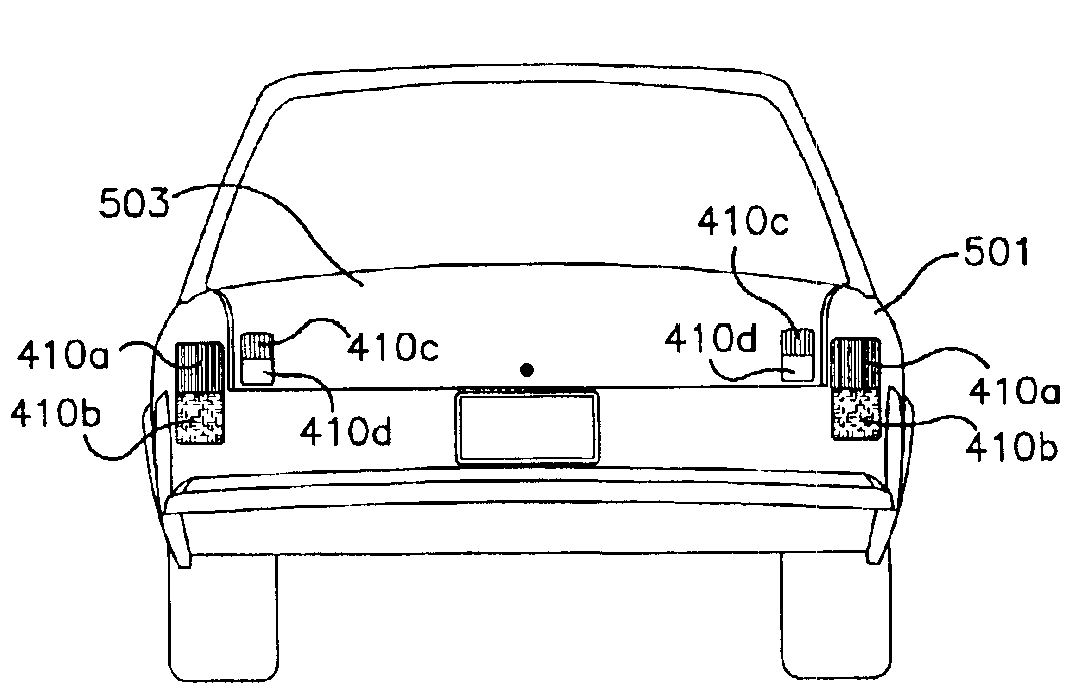
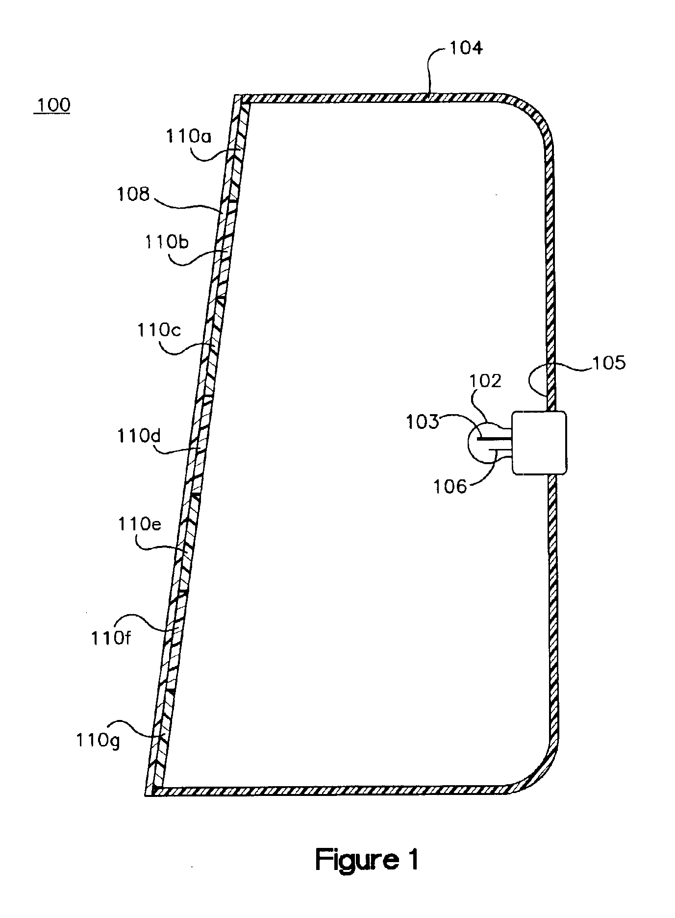
[0026]Turning now to the figures, FIG. 1 illustrates a taillight assembly 100 that includes a light source 102 for emitting light mounted to an enclosure 104 having a light transmissive portion or lens 108 for emitting light from the light source 102 to an illumination zone in front of the taillight assembly 100 but to the back or behind a vehicle to which the taillight assembly is mounted. In a preferred embodiment, the light source 102 is a bulb having two filaments, a major filament 103 and a minor filament 106. An interior surface 105 of the enclosure 104 reflects light reaching the surface 105 back into the enclosure interior so that it will exit the enclosure through the light transmissive portion 108. The light transmissive portion 108 of the enclosure has affixed thereto at specified regions a material. When these regions are electrically energized the material is rendered more light transmissive to alter the amount of light transmitted from the light source 102 to the illum...


PUM

PropertyMeasurementUnit
Pressureaaaaaaaaaa
Transmissionaaaaaaaaaa
Electrical conductoraaaaaaaaaa

Abstract

The present invention relates to a taillight assembly that includes a light source for emitting light and a light source enclosure having a light transmissive portion for transmitting light from the light source to an illumination zone. A portion of the enclosure includes a material that is affixed to selected regions of the light transmissive portion. By electrically energizing the material the light transmitting properties of the material can be altered for performing different taillight functions. A drive circuit is electrically coupled to the material in each region for selectively energizing the material and thereby controlling the functional light output of each region. All taillight functions can be accomplished by activating the bands on the light transmissive portion, including running light, brake light, reverse light, parking light and turning signal.

Description

CROSS-REFERENCE TO RELATED APPLICATIONS[0001]The present application is a non-provisional application claiming the benefit of U.S. Provisional Application, Ser. No. 60 / 441,814 entitled Lamp Masking Method and Apparatus, filed in the United States Patent and Trademark Office on Jan. 22, 2003, and is a continuation in part application containing common subject matter with presently pending U.S. patent application Ser. No. 10 / 442,035, entitled “LAMP MASKING METHOD AND APPARATUS” filed with the United States Patent and Trademark Office on May 20, 2003, which is a continuation in part of U.S. patent application Ser. No. 10 / 419,519 which was filed in the United States Patent and Trademark Office on Apr. 21, 2003 and International Patent Application No. PCT / US02 / 16161 filed May 22, 2002 which are both continuations in part of U.S. patent application Ser. No. 10 / 108,827 which was filed in the United States Patent and Trademark Office on Mar. 27, 2002, now U.S. Pat. No. 6,550,943, issued Apr...

Claims


Application Information

Patent Timeline
IPC IPC(8): B60Q1/12B60Q1/00B60Q1/04B60Q1/26C09K19/60C09K19/02C09K19/54F21V3/00F21V3/04F21V14/00G02F1/133G02F1/13G02F1/1334
CPCB60Q1/00B60Q1/26C09K19/0208C09K19/60F21S48/1731C09K19/542B60Q2400/20G02F2001/13347F21V3/04G02F1/13306F21S41/645G02F1/13347
Inventor STRAZZANTI, MICHAEL
Owner ILLUME
Why Eureka
Try Eureka