Internal low pressure turbine case cooling

a technology of low-pressure turbines and casings, which is applied in the direction of liquid fuel engines, machines/engines, mechanical equipment, etc., can solve the problems of reducing the service life of components, increasing the metal temperature of casings, and reducing the useful life of casing materials

Inactive Publication Date: 2005-06-07
GENERAL ELECTRIC CO
View PDF15 Cites 46 Cited by
  • Summary
  • Abstract
  • Description
  • Claims
  • Application Information

AI Technical Summary

Benefits of technology

[0010]A low pressure turbine casing has a conical annular shell circumscribed about a centerline, a forward flange radially inwardly depending from a forward end of the annular shell, and a forward hook extending axially aftwardly from the forward flange. Axially spaced apart annular first and second rails having first and second hooks, respectively, extend axially aftwardly from the annular shell and are located axially aft of the forward hook. First and second pluralities of first and second cooling holes extend through the first and second rails, respectively. In the exemplary embodiment, a plurality of cooling air feed holes extend through the forward flange. The plurality of cooling air feed holes may be substantially parallel to the centerline. The first and second pluralities of first and second cooling holes may be radially disposed through the first and second rails, respectively, with respect to the centerline or disposed through the first and second rails at an oblique angle with respect to the centerline.

Problems solved by technology

The heat increases the metal temperatures of the casing and in turn reduces the useful life of the casing materials due to low cycle fatigue.
The time-dependent properties of the casing material become limiting and unacceptable permanent casing deformations occur that adversely affect interstage turbine clearances, thereby reducing component service life of the casing.

Method used


Image

  • Internal low pressure turbine case cooling
  • Internal low pressure turbine case cooling
  • Internal low pressure turbine case cooling

Examples


Embodiment Construction

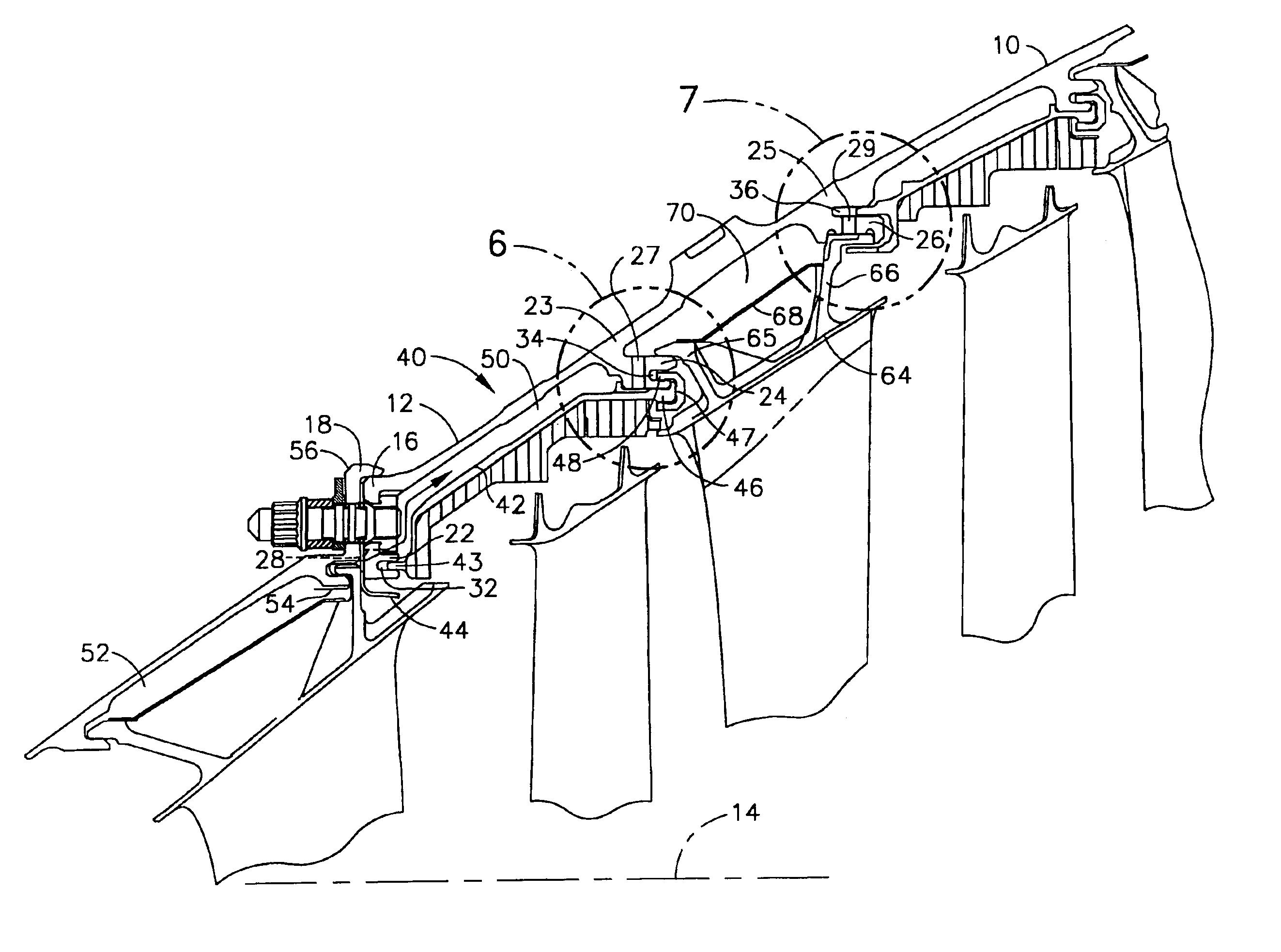
[0026]Illustrated in FIG. 3 is a low pressure turbine casing and shroud assembly 40 having a low pressure turbine casing 10 with a conical annular shell 12 circumscribed about a centerline 14. A forward flange 16 radially inwardly depends from a forward end 18 of the annular shell 12 and a forward hook 22 extends axially aftwardly from the forward flange 16. Referring to FIGS. 3, 6, and 7, axially spaced apart annular first and second rails 23 and 25 having first and second hooks 24 and 26, respectively, extend axially aftwardly from the annular shell 12 and are located axially aft of the forward hook 22. First and second hooks 24 and 26, include first and second annular slots 34 and 36, respectively. First and second pluralities of first and second cooling holes 27 and 29 extend through the first and second rails 23 and 25, respectively allowing cooling air 58 to flow therethrough.

[0027]Referring to FIGS. 4 and 5, a plurality of cooling air feed holes 28 extend through the forward ...


PUM


Abstract

A low pressure turbine casing has a conical annular shell circumscribed about a centerline. A forward flange depends from a forward end of the annular shell and a forward hook extends aftwardly from the forward flange. First and second rails having first and second hooks, respectively, extend aftwardly from the annular shell. First and second cooling holes extend through the first and second rails, respectively. Cooling air feed holes extend through the forward flange. The first and second cooling holes may be radially disposed through the first and second rails, respectively, with respect to the centerline or disposed through the first and second rails at an oblique angle with respect to the centerline. A low pressure turbine casing and shroud assembly further includes a first annular cavity in fluid flow communication with the first cooling holes and the second cooling holes. A second annular cavity is in fluid flow communication with the first and second cooling holes.

Description

BACKGROUND OF THE INVENTION[0001]1. Field of the Invention[0002]This invention relates to cooling of casing of low pressure turbine case of a gas turbine engine and, more particularly, to such cooling by flowing cooling air between shrouds and the case.[0003]2. Description of Related Art[0004]A gas turbine engine of the turbofan type generally includes a forward fan and booster compressor, a middle core engine, and an aft low pressure power turbine (LPT). The core engine includes a high pressure compressor, a combustor, and a high pressure turbine in a serial flow relationship. The high pressure compressor and high pressure turbine of the core engine are interconnected by a high pressure shaft to the high pressure rotor. The high pressure compressor is rotatably driven to compress air entering the core engine to a relatively high pressure. This high pressure air is then mixed with fuel in the combustor and ignited to form a high energy gas stream. The gas stream flows aftwardly and ...

Claims


Application Information

Patent Timeline
Patent Type & Authority Patents(United States)
IPC IPC(8): F01D25/14F01D25/08F01D25/24F02C7/18F02C7/28
CPCF01D25/14
Inventor ANDERSON, JR., HENRY CALVINZEGARSKI, FREDERICK J.THOMPSON, JAMES EDWARDBOSEL, TOD KENNETHHILDEBRAND, KURT THOMAS
Owner GENERAL ELECTRIC CO
Why Eureka
Try Eureka