
Roll-pitch-roll surgical tool

a surgical tool and rolling pin technology, applied in the field of rolling pin surgical tools, can solve the problems millions of dollars annually in hospital residency costs alone, and reducing the cost of hospitalization, and achieving the effect of saving millions of hospital days

Inactive Publication Date: 2005-06-07
INTUITIVE SURGICAL OPERATIONS INC
View PDF26 Cites 349 Cited by
  • Summary
  • Abstract
  • Description
  • Claims
  • Application Information

AI Technical Summary

Benefits of technology

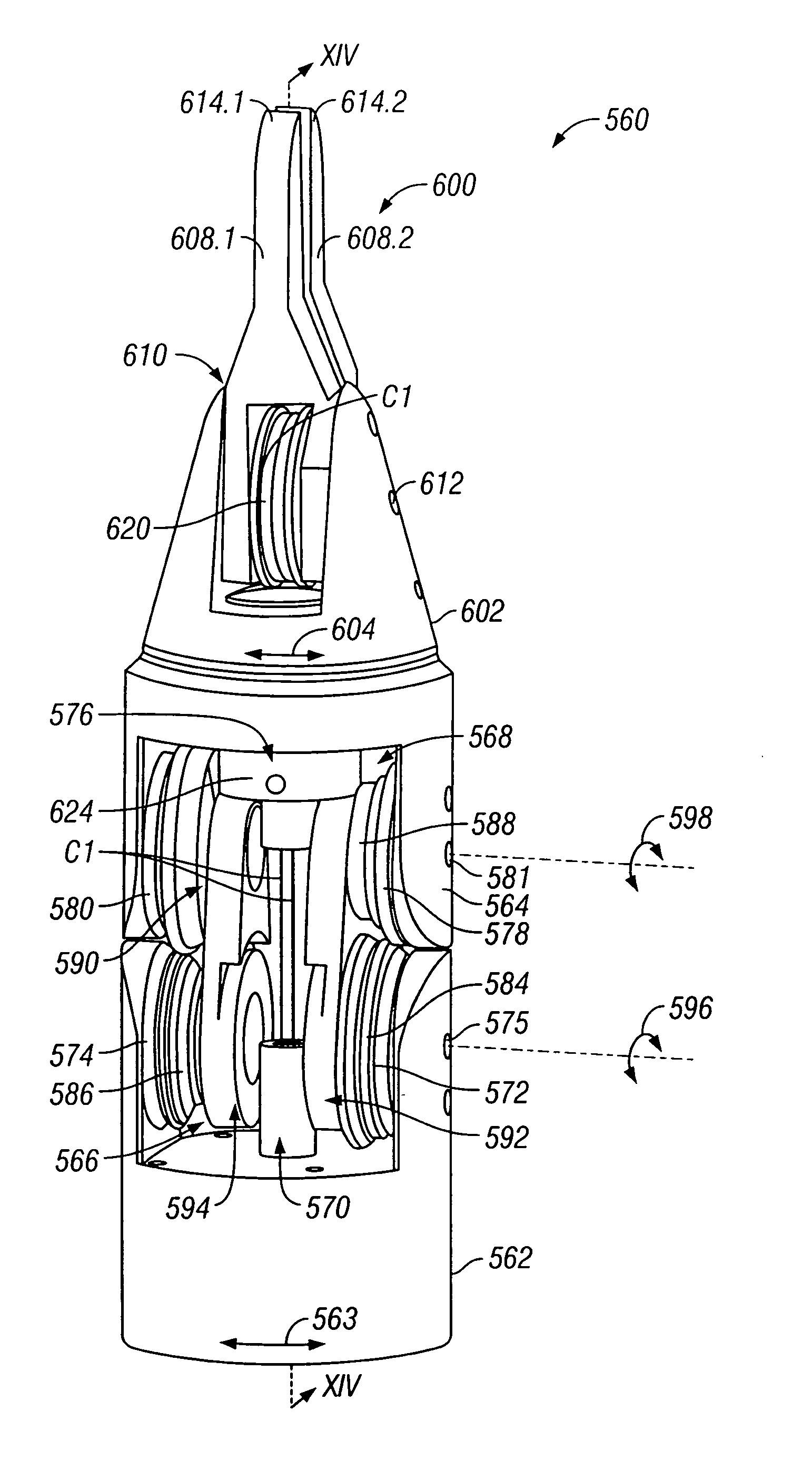
[0009]In some embodiments, the end effector can be bent back beyond 90° pitch. The mechanism coupling the end effector to the working end of the elongate shaft allows the wrist member and end effector to bend back by an angle θ of more than about 90° from the forward position, desirably by more than about 120°, and more desirably by more than about 135°. The ability to operate the end effector at about 90° pitch and to bend back the end effector renders the wrist mechanism more versatile and adaptable to accessing hard to reach locations, particularly with small entry points such as those involving spinal, neural, or rectal surgical sites. In specific embodiments, a pair of linking arms are pivotally connected between the working end and the wrist member to facilitate bend back pitching while maintaining the size of the tool to a sufficiently small size for minimally invasive surgical applications.

Problems solved by technology

Thus, an increased adoption of minimally invasive techniques could save millions of hospital days, and millions of dollars annually in hospital residency costs alone.
There are many disadvantages relating to current minimally invasive surgical (MIS) technology.
For example, existing MIS instruments deny the surgeon the flexibility of tool placement found in open surgery.
Most current laparoscopic tools have rigid shafts, so that it can be difficult to approach the worksite through the small incision.
Additionally, the length and construction of many endoscopic instruments reduces the surgeon's ability to feel forces exerted by tissues and organs on the end effector of the associated tool.
The lack of dexterity and sensitivity of endoscopic tools is a major impediment to the expansion of minimally invasive surgery.
At about 90° pitch, the yaw and roll rotational movements overlap, resulting in the loss of one degree of rotational movement.

Method used


Image

  • Roll-pitch-roll surgical tool
  • Roll-pitch-roll surgical tool
  • Roll-pitch-roll surgical tool

Examples


Embodiment Construction

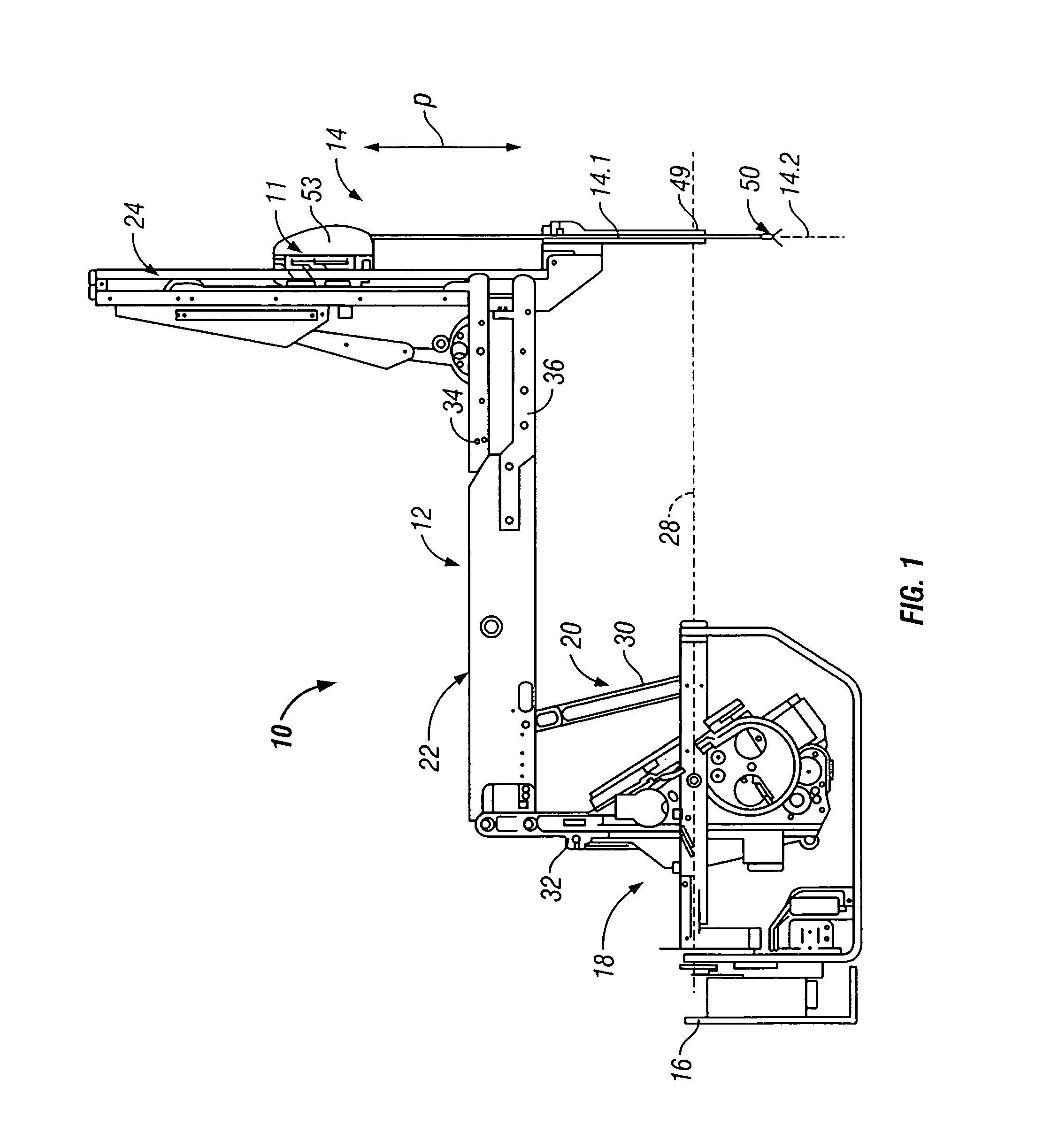
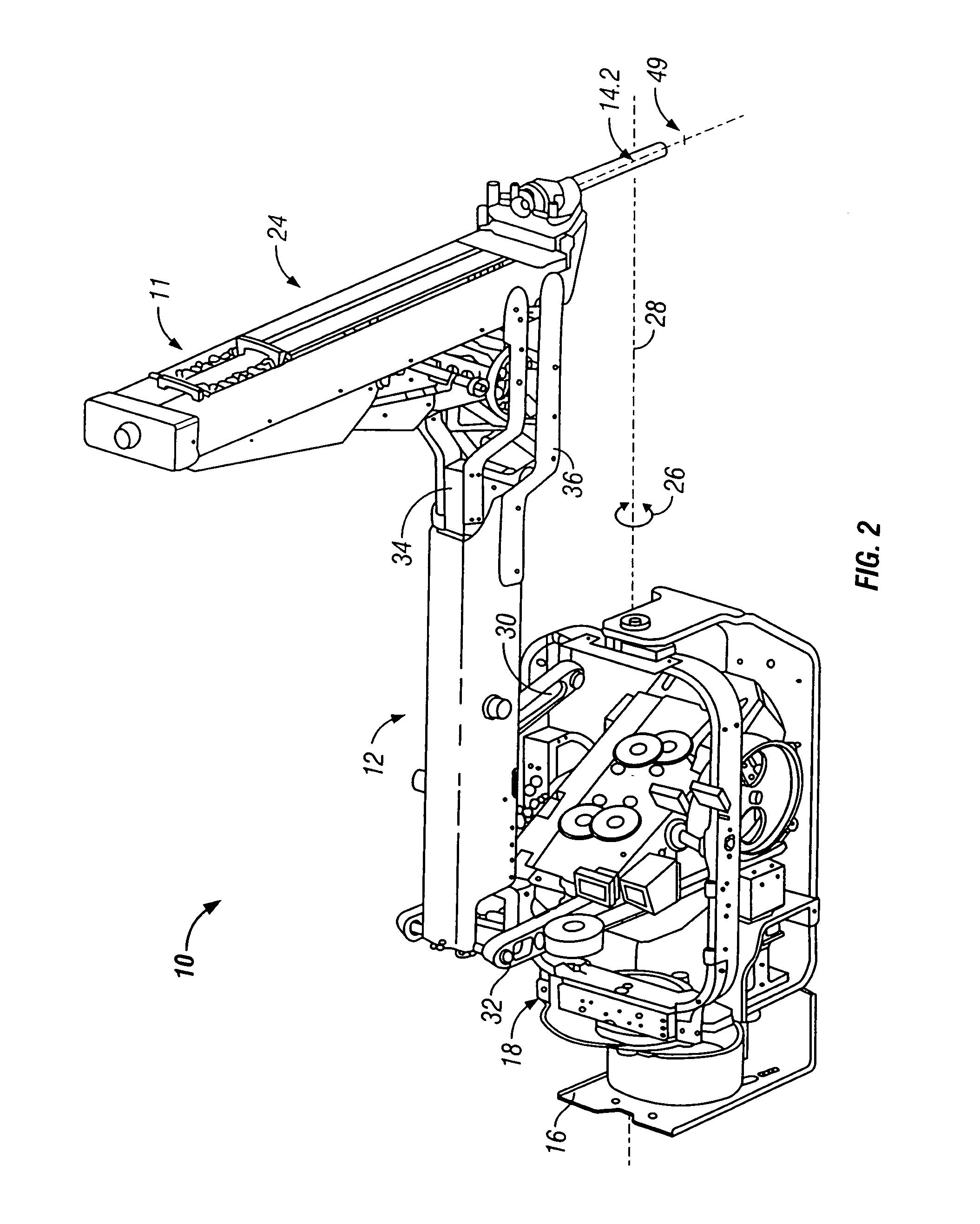
[0032]FIGS. 1 and 2 illustrate a robotic arm and surgical instrument assembly 10. The assembly 10 includes a robotic arm 12 and a surgical instrument 14. FIG. 3 indicates the general appearance of the surgical instrument 14.

[0033]The surgical instrument 14 includes an elongate shaft 14.1. A wrist-like mechanism 50 is located at a working end of the shaft 14.1. A housing 53 arranged releasably to couple the instrument 14 to the robotic arm 12 is located at an opposed end of the shaft 14.1. In FIG. 1, and when the instrument 14 is coupled or mounted on the robotic arm 12, the shaft 14.1 extends along an axis indicated-at 14.2. The instrument 14 is typically releasably mounted on a carriage 11 which is driven to translate along a linear guide formation 24 in the direction of arrows P. The surgical instrument 14 is described in greater detail herein below.

[0034]The robotic arm 12 is typically mounted on a base (not shown) by a bracket or mounting plate 16. The base is typically in the f...


PUM


Abstract

A method of performing minimally invasive endoscopic surgery in a body cavity of a patient includes introducing an elongate shaft having a working end into the cavity. The elongate shaft has a proximal end and a shaft axis between the working end and the proximal end. A wrist member pivotally coupled with the working end is rotated relative to the working end. The wrist member has a wrist axis. The method further includes rotating at least one of the elongate shaft around the shaft axis and an end effector pivotally mounted on the wrist member around the wrist axis to position the end effector at a desired location inside the cavity.

Description

CROSS-REFERENCES TO RELATED APPLICATIONS[0001]This application is a divisional application and claims the benefit of U.S. patent application Ser. No. 10 / 340,129, filed Jan. 10, 2003 now U.S. Pat. No. 6,685,698, which is a divisional of U.S. patent application Ser. No. 09 / 626,527, filed Jul. 27, 2000, now U.S. Pat. No. 6,746,443, the entire disclosures of which are incorporated herein by reference.[0002]This application is related to the following patents and patent applications, the full disclosures of which are incorporated herein by reference: PCT International Application No. PCT / US98 / 19508, entitled “Robotic Apparatus”, filed on Sep. 18, 1998, U.S. application Ser. No. 09 / 418,726, entitled “Surgical Robotic Tools, Data Architecture, and Use”, filed on Oct. 15, 1999; U.S. Application Ser. No. 60 / 111,711, entitled “Image Shifting for a Telerobotic System”, filed on Dec. 8, 1998; U.S. application Ser. No. 09 / 378,173, entitled “Stereo Imaging System for Use in Telerobotic System”, f...

Claims


Application Information

Patent Timeline
Patent Type & Authority Patents(United States)
IPC IPC(8): A61B19/00A61B17/068A61B17/04B25J17/00
CPCA61B17/062A61B19/2203A61B17/00234A61B17/068A61B2019/2234A61B2019/2242Y10T74/20305A61B2017/00477Y10T74/20335Y10T74/2036A61B2019/265A61B34/30A61B34/71A61B2034/305A61B2090/506
Inventor MORLEY, TRACEY A.WALLACE, DANIEL T.
Owner INTUITIVE SURGICAL OPERATIONS INC
Learn More