Directional cooling system for vacuum heat treating furnace

a heat treatment furnace and cooling system technology, applied in the direction of heat treatment apparatus, furnaces, muffle furnaces, etc., can solve the problems of uneven cooling of workpieces, areas that receive too little or too much cooling, and finished workpieces that may not exhibit the desired properties, such as hardness and ductility

Inactive Publication Date: 2005-06-07
IPSEN INT
View PDF5 Cites 14 Cited by
  • Summary
  • Abstract
  • Description
  • Claims
  • Application Information

AI Technical Summary

Benefits of technology

[0007]The above-described problems associated with the known vacuum heat treating furnaces are overcome to a large degree by the vacuum heat treating furnace in accordance with the present invention. According to a first aspect of the present invention, there is provided a heat treating furnace for providing directional cooling of a workpiece load. The heat treating furnace includes a hot zone enclosure defining a hot zone therein. The hot zone enclosure has a side wall, a first end wall, and a second end wall. The side wall has one or more slots formed therethrough and along the length thereof. The heat treating furnace also includes means for injecting a cooling gas into the hot zone through the hot zone enclosure. The heat treating furnace further includes means for directing the cooling gas to exit the hot zone enclosure through one or more of the slots.

Problems solved by technology

One problem with known vacuum treating furnaces occurs when the workpiece is not cooled uniformly.
In many furnaces, the stream of cooling gas contacts one part of the workpiece load more than other parts, resulting in areas that receive too little or too much cooling.
When workpieces are not cooled uniformly, the finished workpiece may not exhibit the desired properties, such as hardness and ductility.
Non-uniform cooling is a common problem in systems that draw cooling gas to exit ports located at only one end of the hot zone.
Non-uniform cooling is also a problem in furnaces where the flow of cooling gas is fixed in one configuration that cannot be adjusted or adapted to cool workpieces having different sizes and geometries.
As a result, the cooling gas stream is drawn to one section of the hot zone, which still results in uneven cooling along the length of the workpiece.
Another problem with known directional cooling systems is the placement of actuators, dampers, and other moving components in the hot zone.
When moving components are routinely exposed to high temperatures in the hot zone, the components become damaged over time, increasing maintenance and equipment downtime.
As a result, the known vacuum heat treating furnaces and cooling systems fall short of the needs of furnace users who desire uniform cooling of workpieces and reduced maintenance of their vacuum furnaces.

Method used


Image

  • Directional cooling system for vacuum heat treating furnace
  • Directional cooling system for vacuum heat treating furnace
  • Directional cooling system for vacuum heat treating furnace

Examples


Embodiment Construction

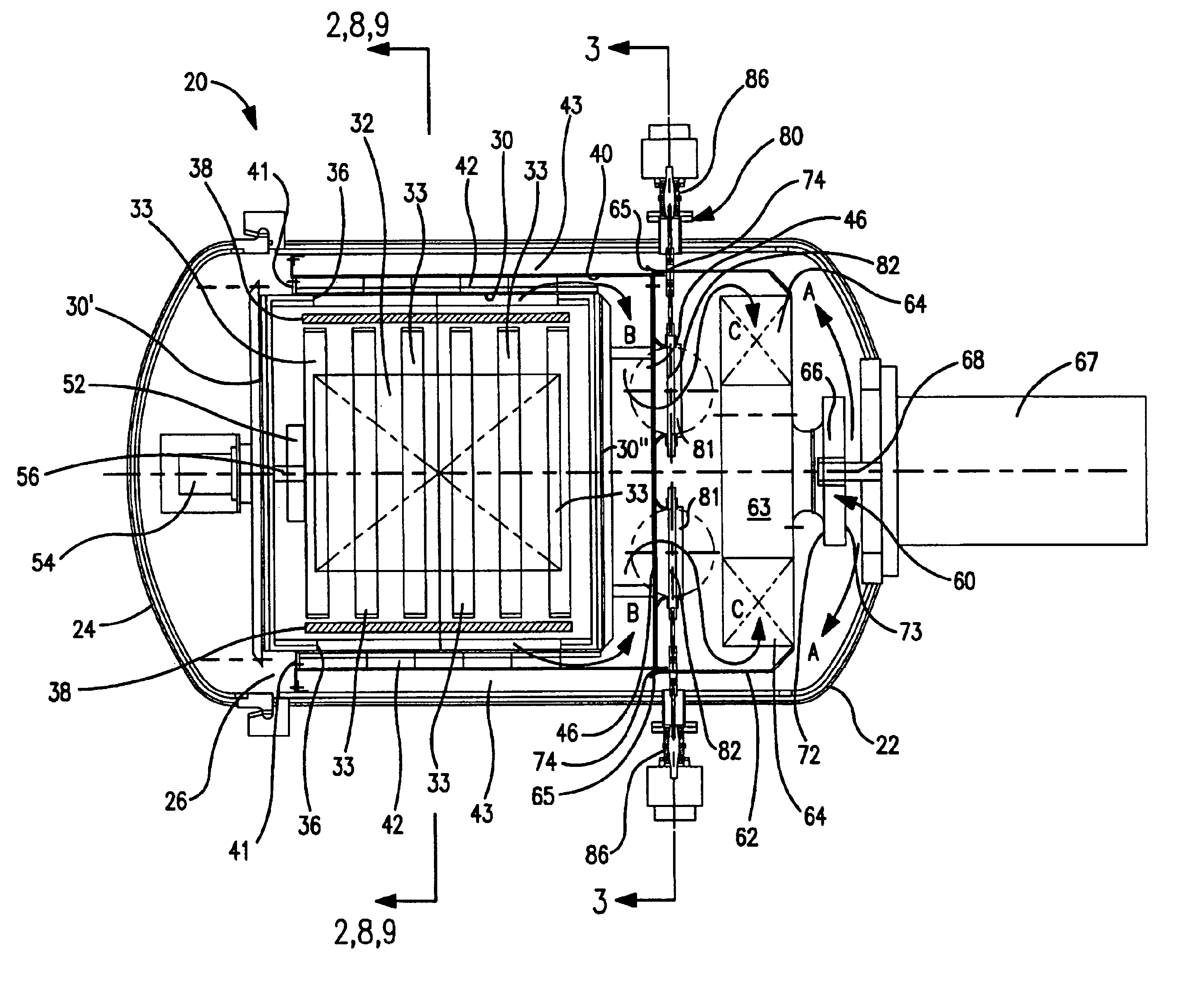
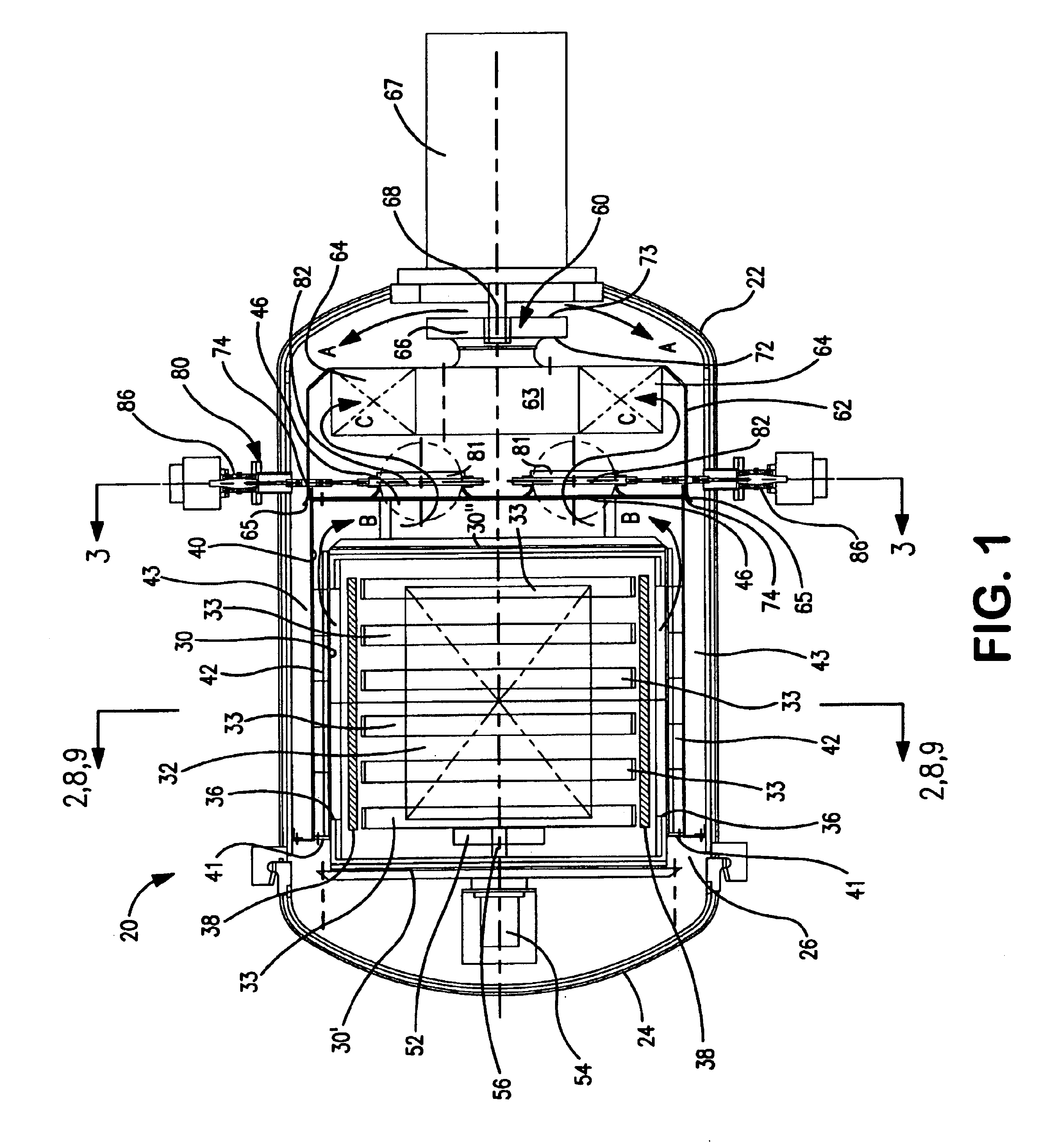
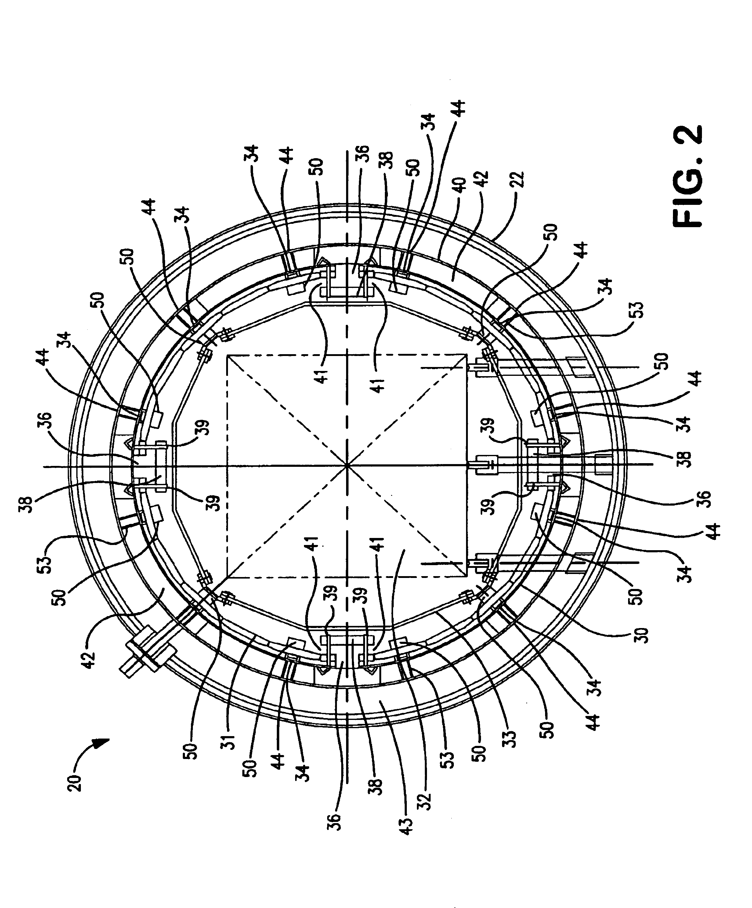
[0019]Referring now to the drawings, a heat treating furnace in accordance with the present invention is shown and designated generally as 20. The heat treating furnace 20 has a hot zone 32 that includes a side wall 30, a first end wall 30′ and a second end wall 30″. Cooling gas can be injected into the hot zone 32 and onto a workpiece from several angles relative to the workpiece. The cooling gas is injected through a plurality of nozzles 50 installed through the side wall 30. The side wall 30 has one or more elongated slots 36. In this manner the cooling gas is caused to flow uniformly over the length of the workpiece to provide efficient removal of heat and improve front to back cooling uniformity.

[0020]A damper assembly 80 is provided to control the direction and flow rate of the cooling gas stream through the hot zone 32. The damper assembly 80 has two or more dampers 82 that connect the hot zone 32 to a blower unit 60. Each damper 82 is located in proximity to one of the slots...


PUM

PropertyMeasurementUnit
lengthaaaaaaaaaa
temperatureaaaaaaaaaa
hardnessaaaaaaaaaa

Abstract

A furnace for heat treating of metal parts includes a hot zone enclosure defining a hot zone therein. The hot zone enclosure has a side wall, a first end wall, and a second end wall. The side wall has slots formed therethrough and along the length thereof. The heat treating furnace also includes a system for injecting a cooling gas into the hot zone through the hot zone enclosure. The heat treating furnace further includes a damper arrangement for directing the cooling gas over a selected portion or portions of the workpiece load and through one or more of the slots. In one embodiment of the invention, all actuated components in the furnace are located outside of the hot zone to minimize damage to moving parts that are caused by exposure to extreme heat.

Description

RELATED APPLICATIONS[0001]This continuation-in-part application claims priority under 35 U.S.C. §120 to U.S. application Ser. No. 10 / 154,457, filed May 23, 2002, which claims priority to U.S. application Ser. No. 09 / 597,496, filed Jun. 20, 2000, both of which are incorporated herein by reference in entirety.FIELD OF THE INVENTION[0002]The present invention relates to vacuum heat treating furnaces, and more specifically to a vacuum heat treating furnace having a precision-controlled, directional cooling system that provides uniform cooling of a workpiece load.BACKGROUND[0003]Known vacuum heat treating furnaces employ cooling gas injection systems to rapidly cool workpieces from the heat treating temperature. The workpieces are heated in a hot zone which is enclosed by a hot zone wall that retains heat inside the hot zone. After heat treatment, cooling gas is injected into the hot zone to cool the workpieces. The cooling gas flows across the hot zone to cool the workpieces and exits t...

Claims


Application Information

Patent Timeline
Patent Type & Authority Patents(United States)
IPC IPC(8): F27B5/00F27B5/16F27B5/06
CPCF27B5/16F27B2005/062
Inventor MOLLER, CRAIG A.
Owner IPSEN INT
Why Eureka
Try Eureka