Moving stage device in exposure apparatus

a technology of moving stage and exposure apparatus, which is applied in the direction of photomechanical apparatus, instruments, printing, etc., can solve the problems of large heat generation during acceleration and deceleration, deformation of a component around the workpiece, and difficulty in cooling the whole stator of the linear motor, so as to increase the control time and reduce the productivity. , the effect of high precision motion

Inactive Publication Date: 2005-06-07
CANON KK
View PDF22 Cites 28 Cited by
  • Summary
  • Abstract
  • Description
  • Claims
  • Application Information

AI Technical Summary

Benefits of technology

[0015]Only when the period of reciprocation is very long, during a period after the stage and the spring are disengaged from each other and before they engage again, simple harmonic oscillation of the spring can be rectified such that heat generation in repeated reciprocation motion can be reduced.
[0017]Since the acceleration and deceleration periods in the exposure apparatus are very short, such state continues until the spring and the stage are disengaged from each other after they engage with each other. Namely, external disturbance of the frequency of simple harmonic oscillation of the spring itself is mixed into the force to be applied by the spring to the stage. Thus, at the moment of the end of acceleration, there remains a positional deviation corresponding to the amount that can not be suppressed by a servo system. This leads to an increase of the control time before start of the exposure operation, and a decrease of the productivity.
[0018]It is accordingly an object of the present invention to provide a moving stage device, a method of moving a moving stage and / or an exposure apparatus, by which high precision motion and high speed motion can be accomplished simultaneously.
[0019]It is another object of the present invention to provide acceleration means by which large thrust and small or null heat generation can be accomplished simultaneously.

Problems solved by technology

However, heat generation during acceleration and deceleration is large, and the source of heat generation is close to the workpiece.
It is difficult to cool the whole stator of the linear motor.
This causes problems of deformation of a component around the workpiece due to thermal expansion, deformation of a measurement reference due to thermal expansion, and disturbance of air density in the light path of the laser interferometer.
On the other hand, in a system in which elastic members such as a coil spring are provided at the opposite ends of the stroke so that only acceleration and deceleration are carried out with use of such elastic members, although heat generation can be removed substantially completely as long as the acceleration and deceleration forces operate normally, there are still two problems.
One problem is that heat generation can be reduced only when the period of reciprocation is very long.
Actually, however, the mass of the spring can not be disregarded.
Thus, the displacement of the spring when the stage engages with the spring again is inaccurate, and the force applied by the spring to the stage varies largely.
Such variation must be compensated for by the linear motor and, as a result, heat generation can not be reduced.

Method used


Image

  • Moving stage device in exposure apparatus
  • Moving stage device in exposure apparatus
  • Moving stage device in exposure apparatus

Examples


first embodiment

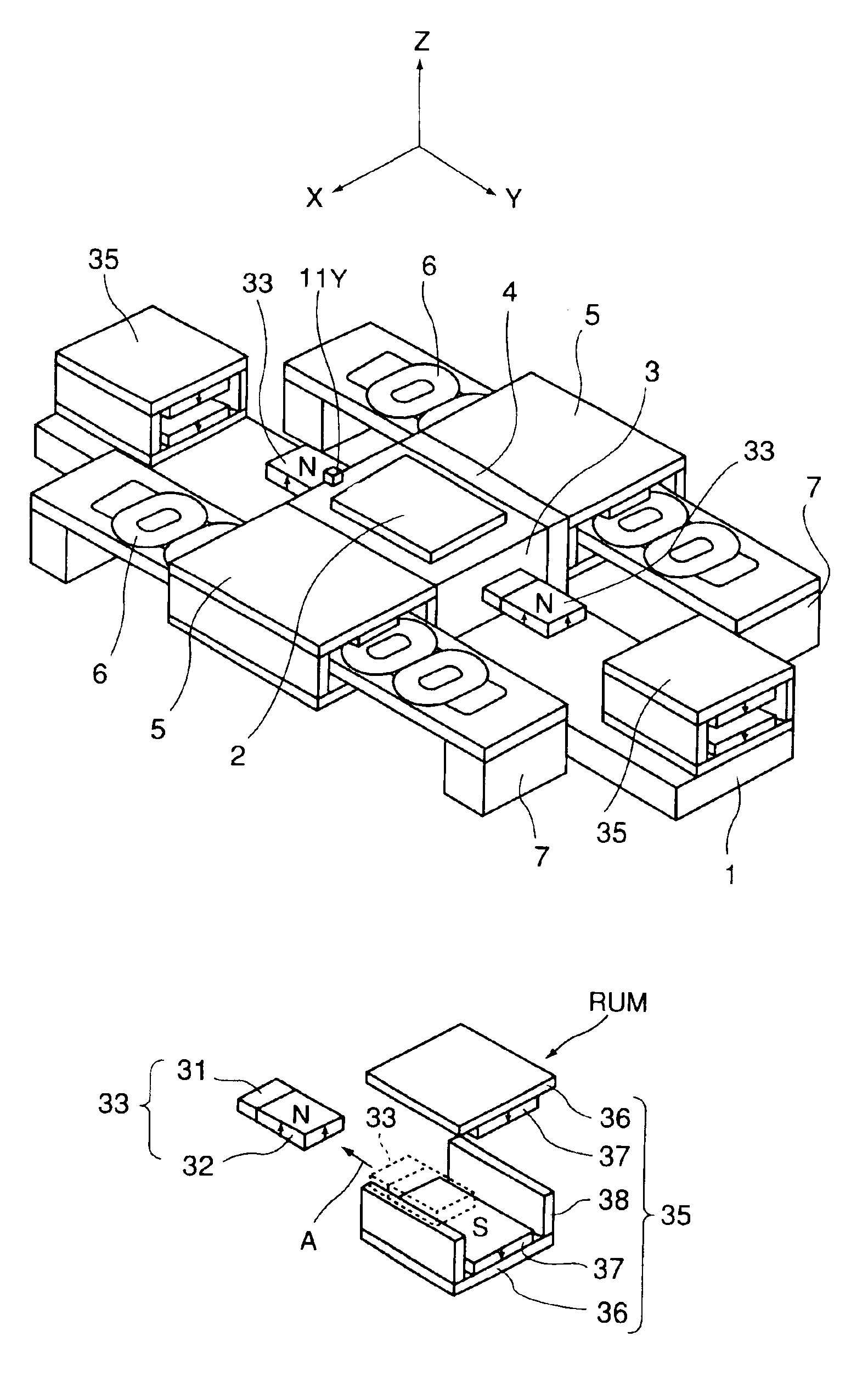
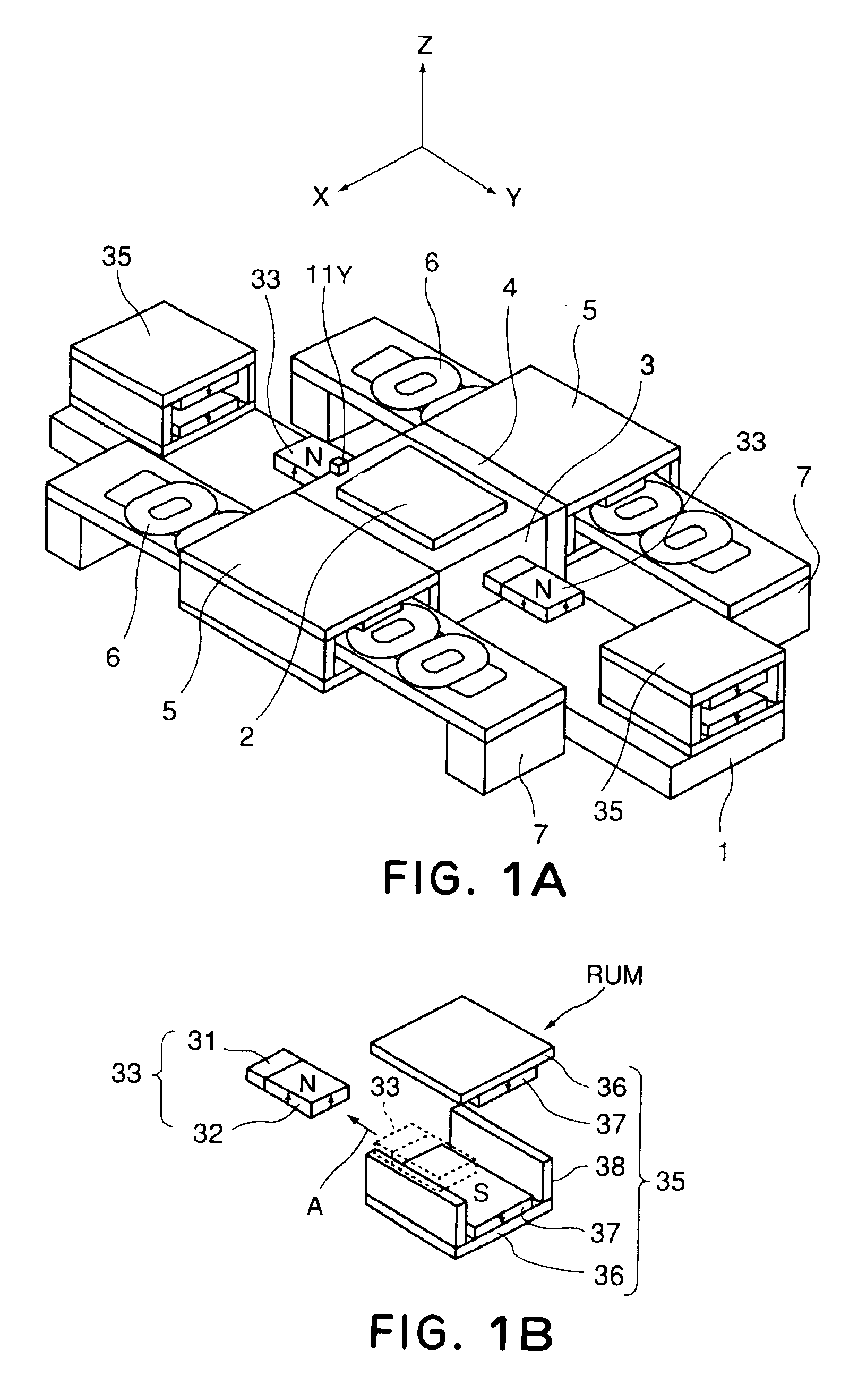
[0058]FIGS. 1A and 1B are perspective views, illustrating a moving stage device according to a first embodiment of the present invention. In this moving stage device, a base guide 1 is fixed to an unshown base, and the base guide 1 supports a stage 3 for carrying thereon a workpiece 2 for sliding movement in one axial direction relative to the base guide 1. The Z tilt motion of the stage 3 is restricted by means of an air slide which is defined between the top face of the base guide 1 and the bottom face of the stage 3. Rotation of the stage 3 about a Z axis which is in a direction perpendicular to or substantially perpendicular to an X-Y plane, as well as the position in X direction which is a direction orthogonal to or substantially orthogonal to a Y direction (movement direction) are restricted by means of an air slide defined between a side face of a yaw guide 4 and a side face of the base guide 1. Fixedly mounted at the opposite sides of the stage 3 are linear motor movable ele...

second embodiment

[0078]FIGS. 4A and 4B are perspective views, respectively, of a moving stage device according to a second embodiment of the present invention. In this moving stage device, a base guide 1 is fixed to an unshown base, and the base guide 1 supports a stage 3 for carrying thereon a workpiece 2 for sliding movement approximately in one axial direction relative to the base guide 1. The Z tilt motion of the stage 3 is restricted by means of an air slide which is defined between the top face of the base guide 1 and the bottom face of the stage 3. Rotation of the stage 3 about a Z axis and the position in X direction are not restricted, but they are free. However, the movable stroke is almost zero. Fixedly mounted at the opposite sides of the stage 3 are linear motor movable elements 5, each being disposed opposed to a linear motor stator 6 without contact thereto. Each stator 6 is fixed to an unshown base.

[0079]The linear motor shown at the front side as seen in the drawing has a similar st...

third embodiment

[0095]FIGS. 7, 8, and 9 are perspective views, respectively, illustrating a third embodiment of the present invention.

[0096]In this moving stage device, a base guide 1 is fixed to an unshown base, and the base guide 1 supports a stage 3 for carrying thereon a workpiece 2 for sliding movement approximately in one axial direction relative to the base guide 1. The Z tilt motion of the stage 3 is restricted by means of an air slide which is defined between the top face of the base guide 1 and the bottom face of the stage 3.

[0097]Rotation of the stage 3 about a Z axis and the position in X direction are not restricted, but they are free. However, the movable stroke is almost zero. Fixedly mounted at the opposite sides of the stage 3 are dual-axis single-phase linear motor movable elements 45. Each of these movable elements is disposed opposed to a pair of linear motor stators 46 without contact thereto, in the manner that the stators 46 sandwich the movable element 45 in the vertical dir...


PUM


Abstract

Disclosed is a stage device by which high precision motion and high speed motion can be accomplished simultaneously. The stage device includes a stage, a repulsive magnet unit for accelerating and / or decelerating the stage with respect to a movement direction, and a magnetic driving system for controlling the position of the stage. The repulsive force generator has (i) a repulsive stator, as a set magnet, including a plurality of magnets disposed along a direction orthogonal or substantially orthogonal to the movement direction, with a spacing therebetween while different poles of them are opposed to each other, and (ii) a repulsive movable element, as an insert magnet, to be mountably and demountably inserted into the spacing and being disposed in relation to the repulsive stator so that the same poles are opposed to each other.

Description

FIELD OF THE INVENTION AND RELATED ART[0001]This invention relates to a moving stage device, a method of moving a moving stage and an exposure apparatus. More particularly, the invention concerns a moving stage device to be controlled very precisely.[0002]FIG. 10 is a general and perspective view of a conventional moving stage device, and FIG. 11 is a block diagram of a control system of the same. FIGS. 12A-12D are schematic views, respectively, including three drawings of a peripheral portion of a linear motor.[0003]In FIG. 10, a base guide 1 is fixed to an unshown base, and the base guide 1 supports a stage 3 for carrying thereon a workpiece 2 for sliding movement in one axial direction relative to the base guide 1. The motion of the stage 3 in a Z tilt direction is restricted by means of an air slide which is defined between the top face of the base guide 1 and the bottom face of the stage 3. Rotation of the stage 3 about a Z axis is restricted by means of an air slide defined be...

Claims


Application Information

Patent Timeline
Patent Type & Authority Patents(United States)
IPC IPC(8): G03B27/48H02K33/00H01L21/027H02K41/03
CPCG03F7/70758G03B27/48
Inventor KORENAGA, NOBUSHIGE
Owner CANON KK
Why Eureka
Try Eureka