Electronically commutated DC motor comprising a bridge circuit

a bridge circuit and electric commutation technology, applied in the direction of multiple dynamo-electric motor speed regulation, synchronous motor starters, multiple dynamo-electric motors, etc., can solve the problem of raising the cost of circuit board manufacturing, and achieve the effect of easy and inexpensive manufacturing

Inactive Publication Date: 2005-06-07
EBM PAPST ST GEORGEN & -
View PDF17 Cites 20 Cited by
  • Summary
  • Abstract
  • Description
  • Claims
  • Application Information

AI Technical Summary

Benefits of technology

[0007]According to the invention, this object is achieved by providing a control transistor serving to logically combine the rotor position signals, a first rotor position signal being applied to the base of the control transistor, a second rotor position signal being applied to the emitter, and the collector signal serving to control the current in an associated stator winding. The control transistor effects a logical combination of two rotor position signals in simple fashion and without separate signal inversion, can additionally serve as a level converter as necessary, and allows reciprocal locking of the upper and lower bridge transistors of a bridge arm. The circuit is simplified by way of the invention in such a way that the requisite circuit board can be manufactured easily and inexpensively even for small motors; and installation space is obtained, as applicable, for additional motor functions.

Problems solved by technology

This results in complex circuits having many components, making it difficult, in the context of small motors, to accommodate the circuit board in the motor housing, and raising the cost of manufacturing the circuit boards (and therefore the motors), since multi-layer circuit boards are required.

Method used


Image

  • Electronically commutated DC motor comprising a bridge circuit
  • Electronically commutated DC motor comprising a bridge circuit
  • Electronically commutated DC motor comprising a bridge circuit

Examples


Embodiment Construction

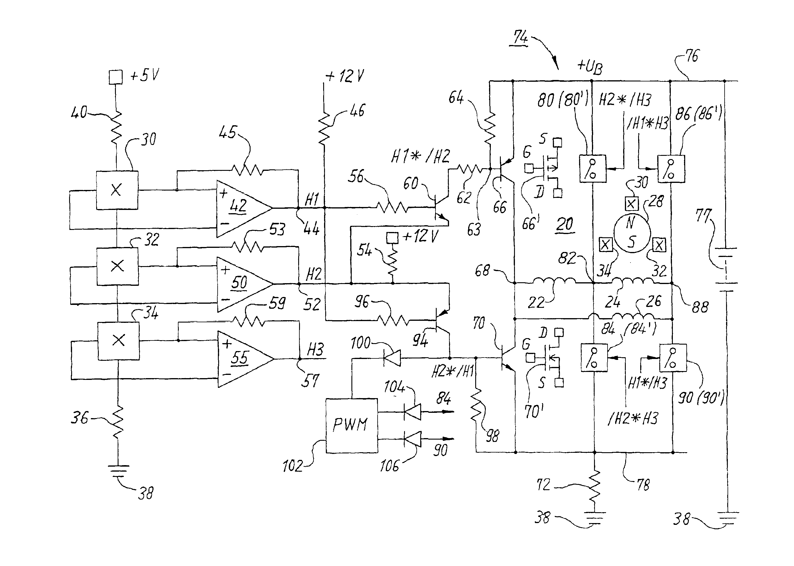
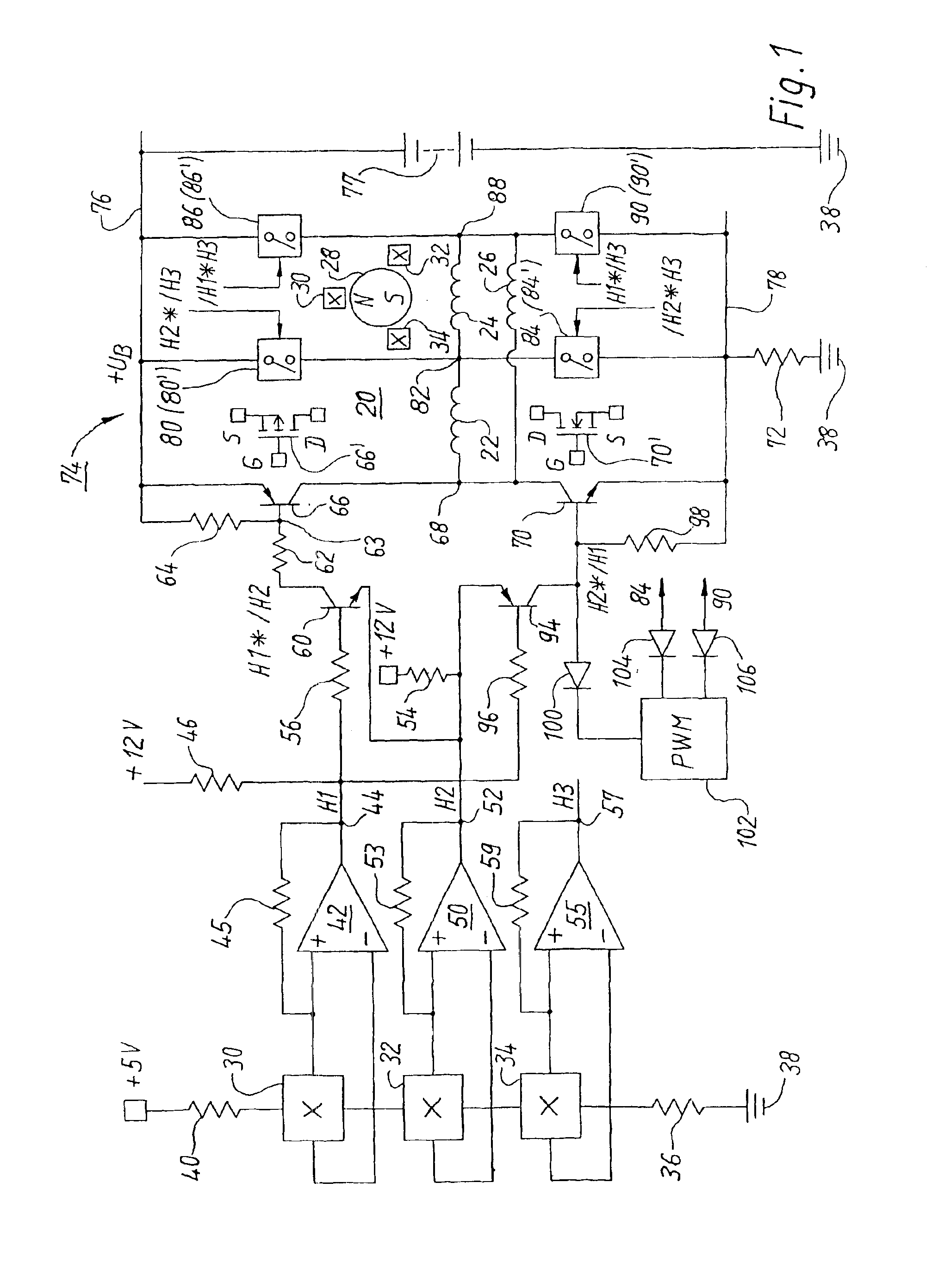
[0017]FIG. 1 shows, at the right, an electronically commutated motor 20 having three stator winding phases 22, 24, 26 and a symbolically indicated permanent-magnet rotor 28, depicted with two poles, around which three rotor position sensors 30, 32, 34 are arranged at intervals of 120° el. and furnish signals H1, H2, H3. These three sensors are also depicted at the far left in FIG. 1. They are connected in series. Lower sensor 34 is connected via a resistor 36 to ground 38, while upper sensor 30 is connected via a resistor 40 to a positive potential, e.g. to a regulated auxiliary voltage of +5 V. Resistors 36 and 40 are usually identical in size. Sensors 30, 32, 34 are normally Hall sensors, but any other sensors would also be possible, e.g. optical sensors.

[0018]The two output signals of Hall sensor 30 are conveyed to the inputs of a comparator 42 whose output 44 (with open collector) is connected via a pull-up resistor 46 to an auxiliary voltage of e.g. +12 V, thus providing at out...


PUM


Abstract

An electronically commutated DC motor comprises a stator comprising at least one stator winding (22, 24, 26), a rotor (28) electromagnetically interacting with the stator, a positive and a negative DC voltage line (76, 78) for supplying power to the motor (20), in particular from a battery (77), a full bridge circuit (74) for controlling the current in the at least one stator winding (22, 24, 26), which full bridge circuit (74) comprises a plurality of bridge arms that each comprise an upper bridge transistor (66, 80, 86) for controlling the current from the positive DC voltage line (76) to an associated terminal (68; 82; 88) of that stator winding (22, 24, 26) as well as a lower bridge transistor (70, 84, 90) for controlling the current from the relevant terminal of the stator winding to the negative DC voltage line (78). The motor further comprises an arrangement for generating a plurality of rotor position signals, and an arrangement for controlling a predetermined bridge transistor by logical combination of rotor position signals associated therewith, there being provided, for logical combination of those rotor position signals, a control transistor (60) to whose base a first rotor position signal (H1) is conveyable and to whose emitter a second rotor position signal (H2) is conveyable, and whose collector signal serves to control the predetermined bridge transistor (66). A circuit comprising a half bridge is also described.

Description

CROSS REFERENCE[0001]This application is a section 371 of PCT / EPO3 / 03067, filed 25 Mar. 2003 and published 16 Oct. 2003 in the German language as WO 03-085808-A1. The international application claims priority from German application DE 102 15 895.9, filed 11 Apr. 2002, which is incorporated by reference.FIELD OF THE INVENTION[0002]The invention concerns an electronically commutated DC motor comprising a full bridge circuit.BACKGROUND[0003]In such a motor, a plurality of rotor position signals are generated, and the individual semiconductor switches of the full bridge circuit are controlled by combinations of those rotor position signals. If a first rotor position signal is designated H1 and a second signal H2, then (as an example) one semiconductor switch of the full bridge must be switched on when the one signal H1 has the value 1 and the other signal H2 has the value 0. On the other hand, a different semiconductor switch of the full bridge must be switched on, for example, when H2...

Claims


Application Information

Patent Timeline
Patent Type & Authority Patents(United States)
IPC IPC(8): H02P6/00H02P6/08
CPCH02P6/085H02P6/001H02P6/34
Inventor WEISSER, WILHELMHEYDRICH, WALTERRAPPENECKER, HERMANN
Owner EBM PAPST ST GEORGEN & -
Why Eureka
Try Eureka