
SAW filter and electronic device including SAW filter

Active Publication Date: 2005-06-07
SKYWORKS PANASONIC FILTER SOLUTIONS JAPAN
View PDF9 Cites 20 Cited by
  • Summary
  • Abstract
  • Description
  • Claims
  • Application Information

AI Technical Summary

Benefits of technology

[0006]The SAW filter has a large attenuation amount at a lower side of a pass band of the filter, thus having sufficient properties.

Problems solved by technology

The attenuation profile of the conventional SAW filter is not sufficient particularly at a lower side of the pass band.

Method used


Image

  • SAW filter and electronic device including SAW filter
  • SAW filter and electronic device including SAW filter
  • SAW filter and electronic device including SAW filter

Examples


Embodiment Construction

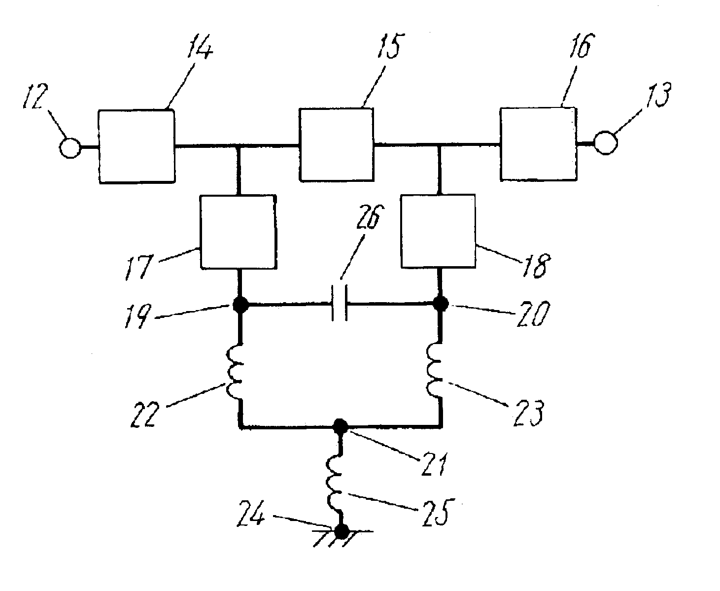
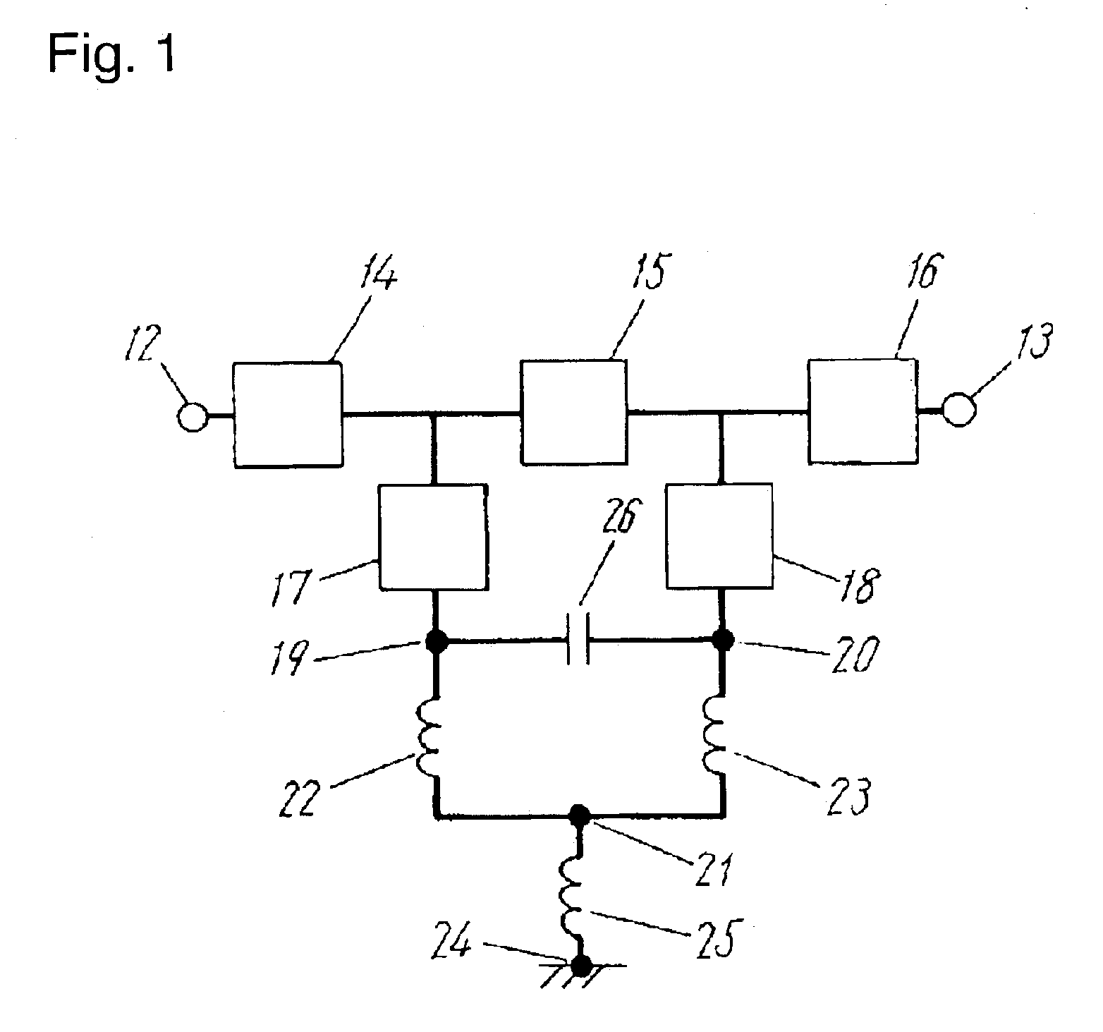
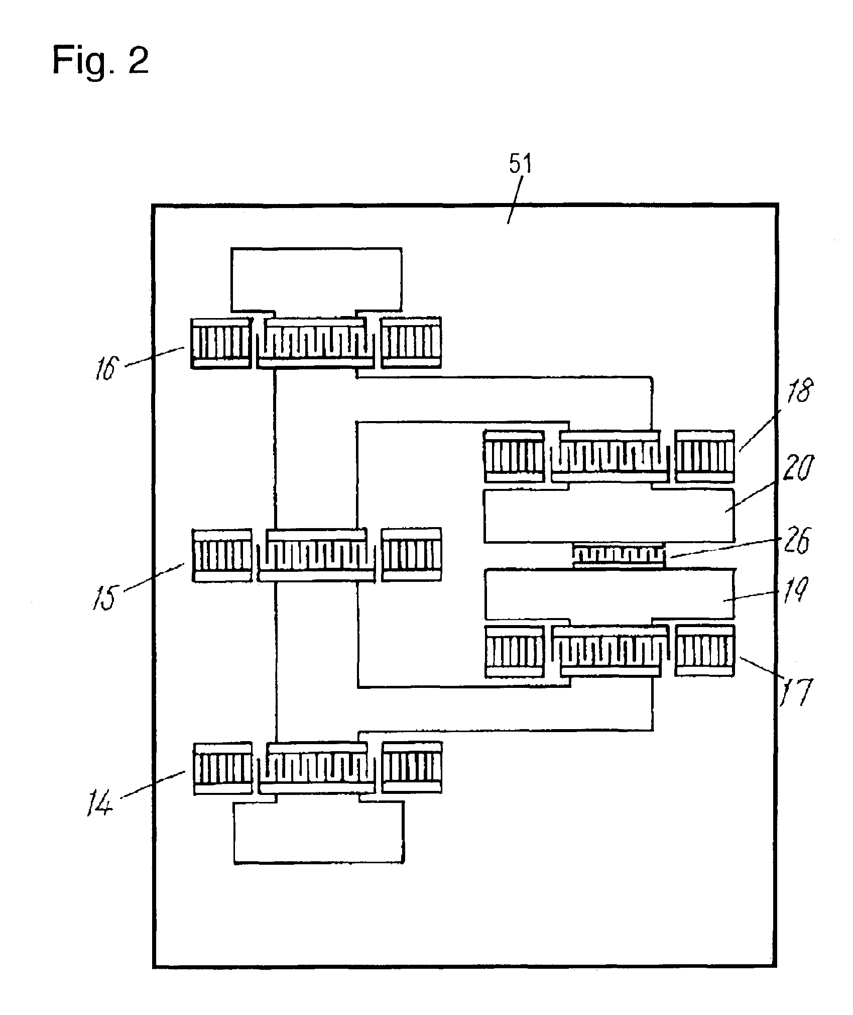
[0017]FIG. 1 illustrates a circuit diagram of a surface acoustic wave (SAW) filter according to an exemplary embodiment of the present invention. Series resonators 14, 15, and 16 are connected in series in this order between an input terminal 12 and an output terminal 13. Parallel resonators 17 and 18 have respective one ports connected to respective ports of the series resonator 15. The parallel resonators 17 and 18 have respective other ports connected to a first grounding node 19 and a second grounding node 20. A first inductance element 22 is connected between the first grounding node 19 and a third grounding node 21 while a second inductance element 23 is connected between the second grounding node 20 and the third grounding node 21. A third inductance element 25 is connected between the third grounding node 21 and a grounding terminal 24. A capacitance element 26 is connected between the first grounding node 19 and the second grounding node 20.

[0018]A characteristic profile of...


PUM


Abstract

A surface acoustic wave (SAW) filter includes an input terminal, an output terminal, a series resonator provided between the input terminal and the output terminal, first and second parallel resonators having respective one ports connected to respective ports of the series resonator, respectively, first and second nodes connected to respective other ports of the first and second parallel resonators, respectively, first and second inductance elements having respective one ends connected to the first and second nodes, respectively, a third node connected to respective other ends of the first and second inductance elements, a third inductance element having one end connected to the third node, a grounding terminal connected to other end of the third inductance element, and a capacitance element connected between the first and second nodes. The SAW filter has a large attenuation amount at a lower side of a pass band of the filter, thus having sufficient properties.

Description

FIELD OF THE INVENTION[0001]The present invention relates to a SAW filter and an electronic device including the SAW filter for use in a communications apparatus.BACKGROUND OF THE INVENTION[0002]In a conventional ladder-type surface acoustic wave (SAW) filter, as shown in FIG. 10, series resonators 3, 4, and 5 are connected in series between an input terminal 1 and an output terminal 2, and parallel resonators 6 and 7 are connected to respective ports of the series resonator 4. The parallel resonators 6 and 7 are connected to inductance elements 8 and 9, respectively. The inductance elements 8 and 9 are connected to one end of an inductance element 10. The other end of the inductance element 10 is connected to a grounding terminal 11.[0003]A characteristic profile of the conventional ladder-type SAW filter having the above-described arrangement is shown by a line B in FIG. 4. As shown as the line B, the conventional SAW filter has a wide pass band and has a attenuation profile of an...

Claims


Application Information

Patent Timeline
IPC IPC(8): H03H9/00H03H9/25H03H9/72H03H9/64H03H9/05
CPCH03H9/0542H03H9/14597H03H9/6493H03H9/6483H03H9/6479
Inventor KUSHITANI, HIROSHISEKI, SHUNICHI
Owner SKYWORKS PANASONIC FILTER SOLUTIONS JAPAN
Learn More