Method for repair and replacement of combustor liner panel

a combustor and liner panel technology, applied in manufacturing tools, forging/pressing/hammering apparatus, lighting and heating apparatus, etc., can solve the problems of low cycle fatigue life, inability to repair welds, and cracks in inner liners after engine use, etc., to achieve cost saving, less expensive, and durable

Active Publication Date: 2006-02-02
GENERAL ELECTRIC CO
View PDF18 Cites 19 Cited by
  • Summary
  • Abstract
  • Description
  • Claims
  • Application Information

AI Technical Summary

Benefits of technology

[0011] An advantage of the present invention is that the damaged portion of the aft panel assembly can be removed from the inner liner assembly, while undamaged portions of the aft panel assembly and forward panel and forward bolt flange can be reused. This provides a significant cost savings.
[0012] Another advantage of the present invention is that the method permits replacement of the aft panel, the aft lip and the aft seal with the same material as that removed, or any one of, or all of, the aft panel, the aft lip and the aft seal can be replaced with a different material that has the capability of being joined to the nugget material and the aft panel support leg material. The replacement material can be a less expensive material and / or a more durable than the removed material, but with adequate properties, or the replacement material can have superior materials properties than the removed material.
[0013] Another advantage of the present invention is that the method permits replacement of aft panel assembly material worn at the inner liner leaf seal interface.
[0014] Still another advantage of the present invention is that it permits recovery of portions of the inner liner assembly, which previously were not cost effective to repair and which were discarded.
[0015] Other features and advantages of the present invention will be apparent from the following more detailed description of the preferred embodiment, taken in conjunction with the accompanying drawings which illustrate, by way of example, the principles of the invention.

Problems solved by technology

Recently, inner liners after usage in an engine have experienced cracking in two regions of the aft panel assembly, the multi-hole cooling area of the liner.
The cracks may be due to low cycle fatigue caused by large circumferential temperature gradients that reduce the liner low cycle fatigue life in that region.
Additionally, the number and location of cracks makes it such that the weld repair is not feasible because hole restoration in the multi-hole cooling area is extensive.
At the aft panel flange region, crack repair can result in aft lip distortion and shrinkage.
This is unacceptable as the exit throat diameter of the liner is a critical dimension.
GTD-222 is an expensive alloy, as are other high temperature, oxidation resistant alloys that may be used in this application, and the processing involved in its manufacture adds to the value of the liner.
However, the repair method does not address repair of a portion of the aft panel assembly, which is discarded and replaced.

Method used


Image

  • Method for repair and replacement of combustor liner panel
  • Method for repair and replacement of combustor liner panel
  • Method for repair and replacement of combustor liner panel

Examples


Embodiment Construction

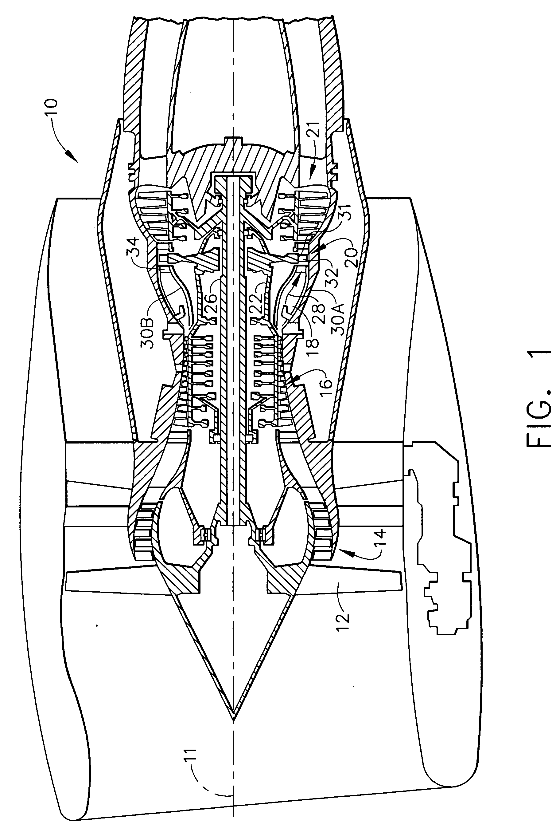
[0020]FIG. 1 is a schematic of a typical high bypass turbine engine 10. The centerline of the engine is shown at 11, along which the engine shaft 26 is positioned. Air enters the engine 10, passing front fan 12. Some of the air enters the engine core 14 and is directed to the compressor section 16 where it is compressed, while the remainder bypasses the engine core. The compressed air enters the combustion chamber, shown at 30A and 30B where it is mixed with fuel metered from the swirl cup of the fuel injector 18 and ignited. The hot gases of combustion proceed toward the rear of the combustion chamber past the turbine vanes or nozzles 34 and into the turbine rotor 20 where turbine blades 32 in the path of the high pressure gases of combustion are mounted on turbine wheels or disks 31. The high pressure gases pushing on the turbine blades 32 turn the wheels 31 which rotate the engine shaft 26. After the hot gases pass through the turbine section 20, they exit the turbine section at ...


PUM

PropertyMeasurementUnit
temperatureaaaaaaaaaa
thrustaaaaaaaaaa
velocityaaaaaaaaaa

Abstract

A method for repairing a damaged portion of a combustor inner liner assembly. The method includes removing the combustor from a gas turbine engine. After inspecting the combustor to determine whether cracks exists in portions of the inner liner assembly, the method includes removing a cracked inner liner assembly from the combustor. Then the portion of the inner liner assembly, comprising a multi-hole panel region, an aft lip region, an aft seal flange region and an aft panel support leg are separated from the inner liner assembly. The multi-hole panel region and aft lip, where fatigue damage typically exists, along with the aft seal flange region, are discarded and a new aft lip region/aft seal flange region and multi-hole panel region are provided. The new parts are joined to the aft panel support leg and the inner liner assembly aft of forward bolt flange region after these parts are refurbished. The inner liner assembly is then reattached to the combustor and reassembled into the engine.

Description

FIELD OF THE INVENTION [0001] The present invention is directed to a method for repair of combustor liner panels, and more specifically to the repair of combustor inner liner panels in large high bypass turbofan engines. BACKGROUND OF THE INVENTION [0002] A turbine engine used to power aircraft typically includes a compressor section for compressing air, a combustor section for mixing the compressed air with fuel and burning it to generate hot gases, a turbine section in which energy is extracted from the hot gases of combustion to operate the compressor and otherwise provide the aircraft and an exhaust section in which the remaining hot gases of combustion of reduced energy pass to provide thrust which propels the aircraft. A turbofan turbine engine further includes a large fan typically located in front of the compressor. In the case of a front fan, the fan is driven by a second turbine, typically the low pressure turbine, located in the turbine section of the engine behind the hi...

Claims


Application Information

Patent Timeline
Patent Type & Authority Applications(United States)
IPC IPC(8): B23P6/00
CPCB23P6/005B23P2700/13F23R3/00F23R3/60F23R2900/00019Y10T29/49746Y10T29/49728Y10T29/4932Y10T29/49721Y10T29/49318Y10T29/4973Y10T29/49346
Inventor CALDWELL, JAMES M.EMILIANOWICZ, EDWARD JOHNLOVELESS, GARY
Owner GENERAL ELECTRIC CO
Why Eureka
Try Eureka