Illumination system for microscopy and observation or measuring method using the same

a technology of illumination system and microscopy, which is applied in the direction of fluorescence/phosphorescence, analysis by material excitation, instruments, etc., can solve the problems of low speed, difficult balance control, and inability to achieve simultaneous illumination with a plurality of wavelengths, and achieve the effect of minimal fading

Inactive Publication Date: 2005-06-07
EVIDENT CORP
View PDF3 Cites 0 Cited by
  • Summary
  • Abstract
  • Description
  • Claims
  • Application Information

AI Technical Summary

Benefits of technology

[0018]Still further, according to the illumination system of the present invention, a fluorescent image which has minimal fading and is bright can be obtained.

Problems solved by technology

This is attributable to problems that much time is required for changeover in excitation wavelength, the changeover of the excitation filter is required, vibration occurs, and simultaneous illumination cannot be achieved with a plurality of wavelengths.
In this case, however, the problems arise that a switching speed is low, it is hard to control the balance between the intensities of excitation light with two wavelengths, and a mechanical vibration is produced when the filter is switched.
When the caged indicator is used, a costly UV laser has been required for irradiation.
Since it is difficult to rotate the filter wheel at a high speed, the improvement of time resolution is impaired.
Furthermore, in the conventional microscope, as disclosed in German Patent Laid-Open Specification No. 2,626,540, a reflecting interference microscope can be used to form an image, but it is not easy to switch the illumination wavelength of reflecting interference.
Moreover, the use of a plurality of costly band-pass filters involves a large expense.

Method used


Image

  • Illumination system for microscopy and observation or measuring method using the same
  • Illumination system for microscopy and observation or measuring method using the same
  • Illumination system for microscopy and observation or measuring method using the same

Examples


first embodiment

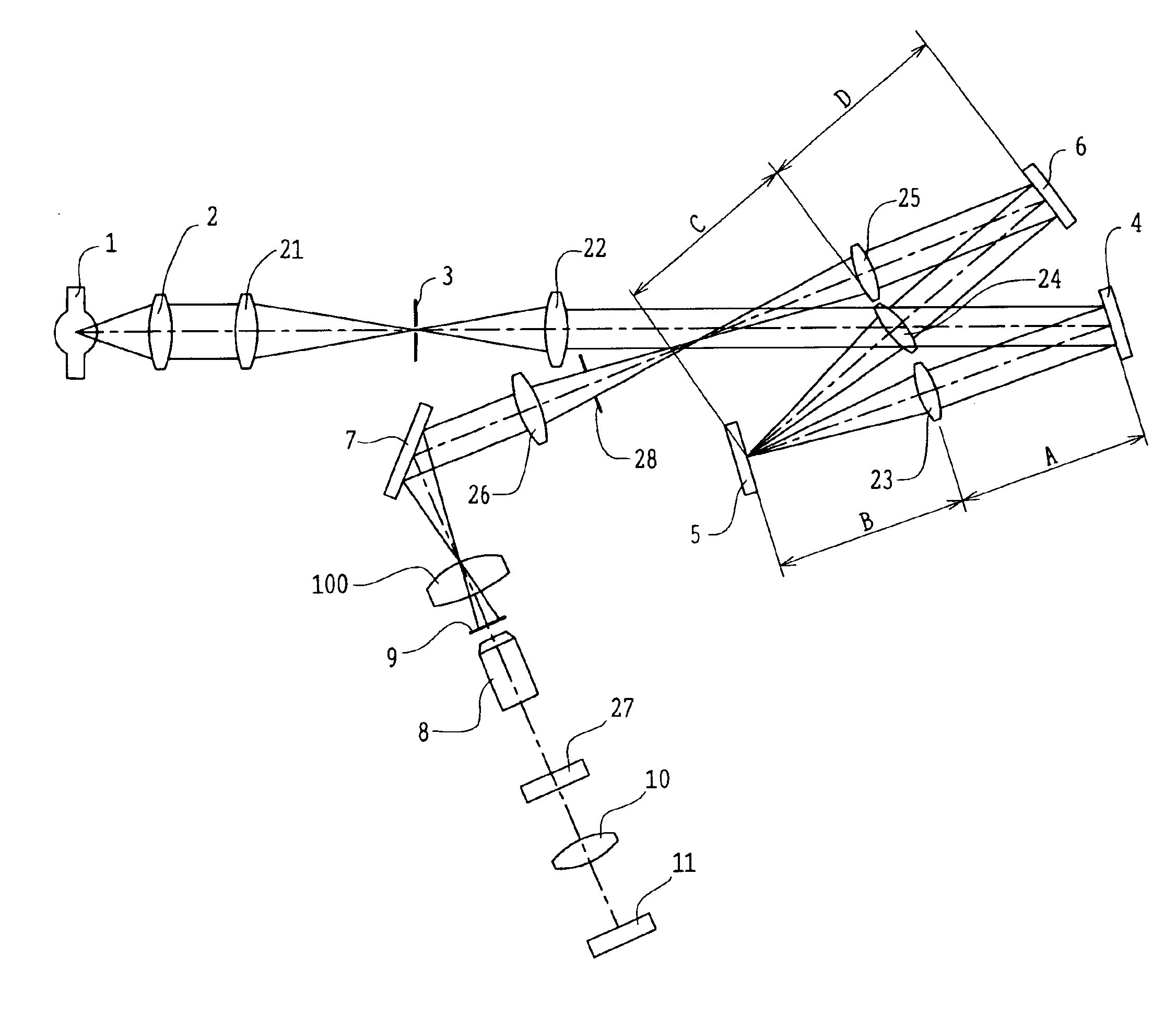
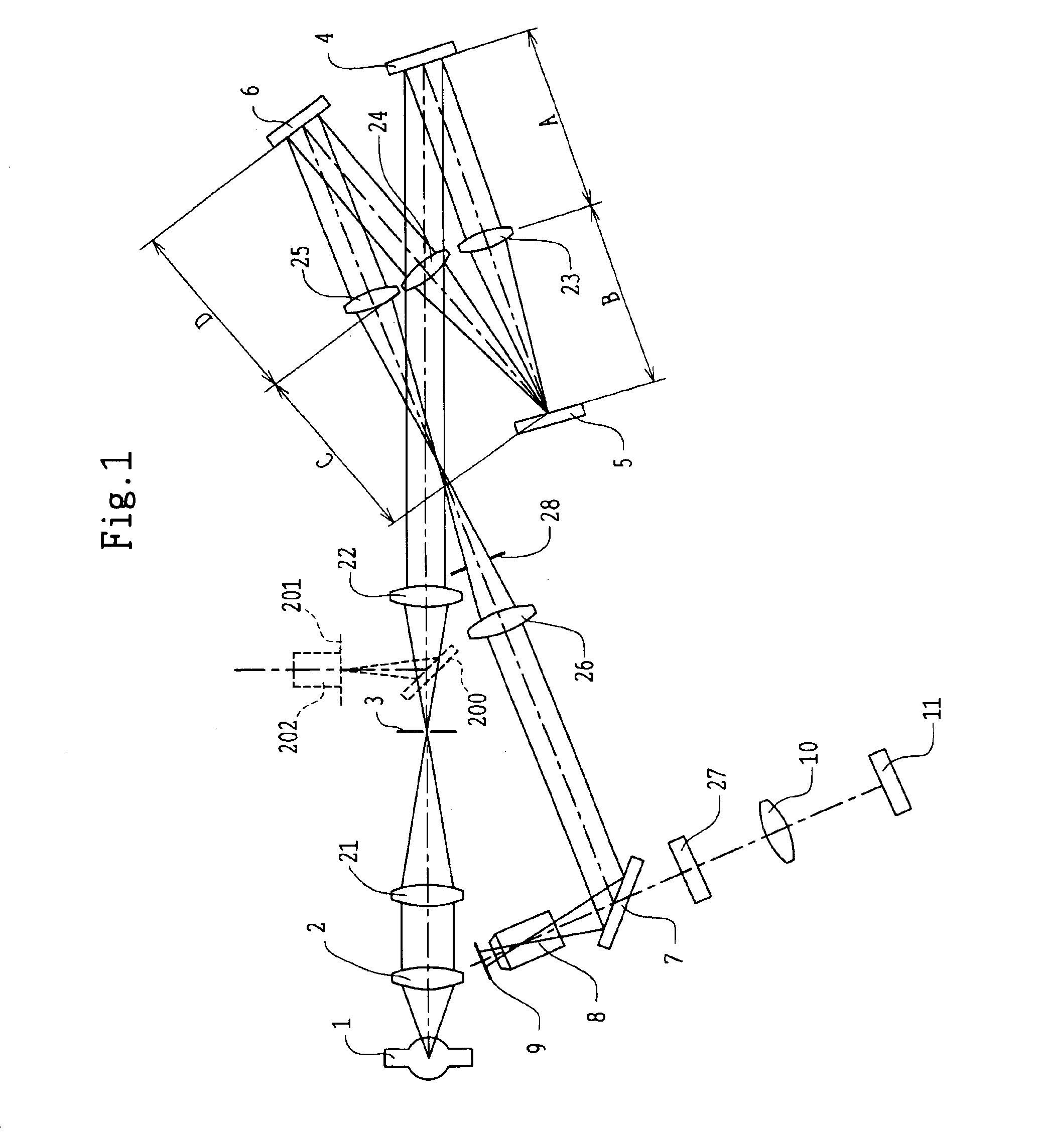
[0058]FIG. 1 shows the first embodiment of the illumination system for microscopy according to the present invention. The illumination system of the first embodiment has a spectral illumination device using gratings as the spectral elements.

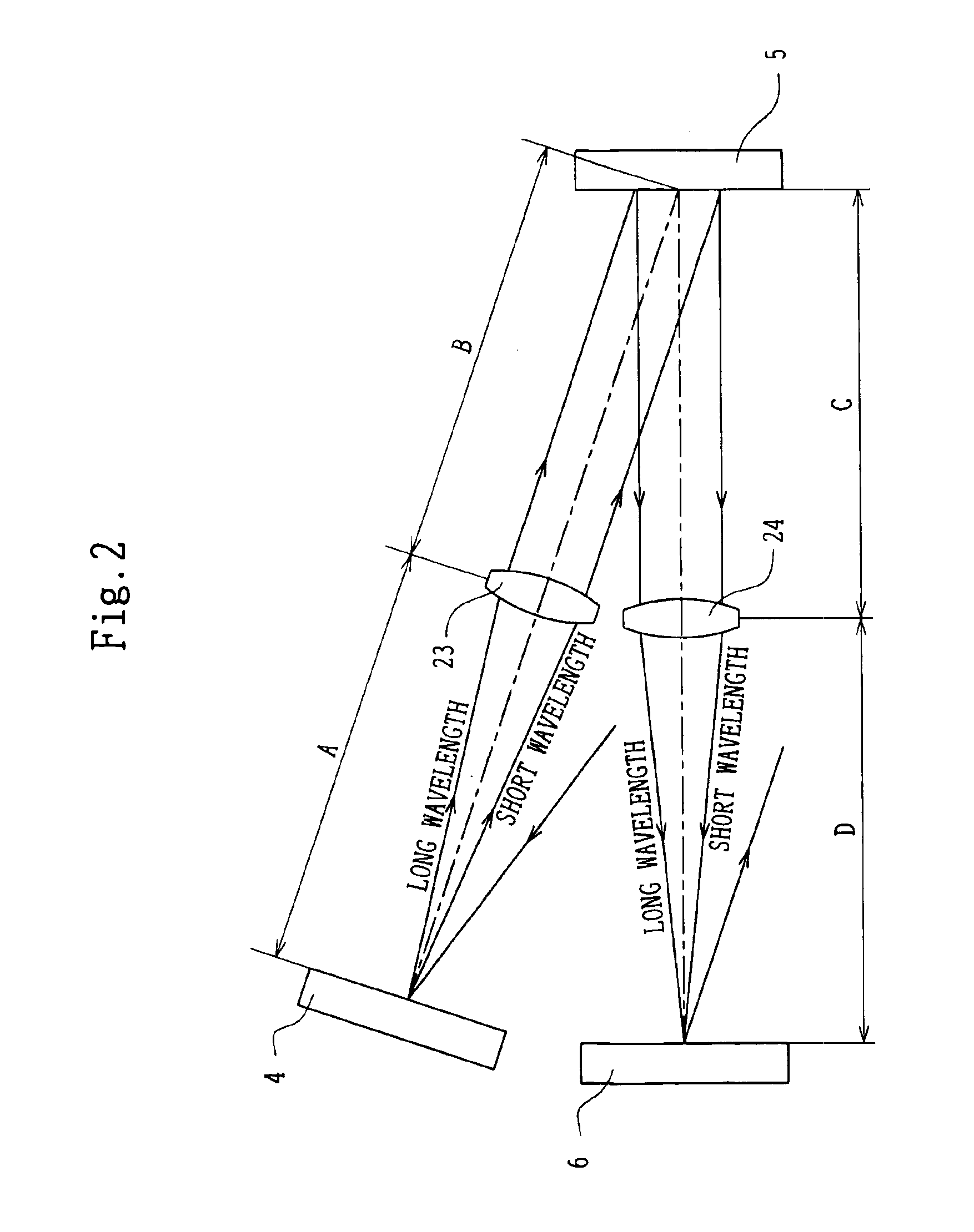
[0059]Light emitted from the light source 1 is condensed through the collector lens 2 and a projection lens 21, and is imaged once at the position of the stop 3 provided with a rectangular aperture or a pinhole aperture to form a lamp image. After that, the light passing through the stop 3 is incident on a lens 22 and is projected through the lens 22 at infinity. The light projected at infinity is incident on the grating 4 and is dispersed (wavelength-dispersed), as shown in FIG. 2, extending from a short wavelength to a long wavelength. Dispersed light enters the lens 23 and is conducted to the DMD 5.

[0060]FIG. 3A shows a slit of rectangular shape, located at the position of the stop. FIG. 3B shows places of incidence of the dispersed light on t...

second embodiment

[0072]FIG. 5 shows the second embodiment of the illumination system for microscopy according to the present invention. The illumination system of the second embodiment has a spectral illumination device using prisms as the spectral elements.

[0073]Light emitted from the light source 1 is condensed through the collector lens 2 and the source projection lens 21, and is imaged once in the proximity of the stop 3 provided with a rectangular aperture or a pinhole aperture to form a lamp image. After that, illumination light passing through the stop 3 is projected through the lens 22 at infinity and is dispersed through a prism 41. In this case, dispersion extends from the short wavelength to the long wavelength as in the illumination system of the first embodiment shown in FIG. 2.

[0074]Dispersed light is projected, through the lens 23, on the DMD 5 as the dispersed image of the stop 3. Light selectively reflected by the DMD 5 is transmitted through the lens 24 and is incident on a prism 6...

third embodiment

[0078]FIG. 6 shows the third embodiment of the illumination system for microscopy according to the present invention. The illumination system of the third embodiment has a spectral illumination device using transmission type gratings as the spectral elements.

[0079]Light emitted from the light source 1 is condensed through the collector lens 2 and the source projection lens 21, and is imaged once at the position of the stop 3 provided with a rectangular aperture or a pinhole aperture to form a lamp image. Then, the light passes through the stop 3, and after being projected through the lens 22 at infinity, is dispersed through a transmission type grating 42. In this case, dispersion extends from the short wavelength to the long wavelength as in the illumination system of the first embodiment shown in FIG. 2.

[0080]Dispersed light is incident on the lens 23 and is projected as the image of the stop 3 on the DMD 5. Light selectively reflected by the DMD 5 is transmitted through the lens ...


PUM

PropertyMeasurementUnit
reflectanceaaaaaaaaaa
of wavelengthaaaaaaaaaa
wavelengthsaaaaaaaaaa

Abstract

An illumination system for microscopy includes a light source, a first spectral element dispersing light from the light source, a reflecting member selectively reflecting light dispersed by the first spectral element, a second spectral element combining light reflected by the reflecting member, a dichroic mirror, an objective lens, and an image sensor. The first spectral element is placed at the front focal point of a first lens, the reflecting member is placed at a position where the back focal point of the first lens coincides with the front focal point of a second lens, and the second spectral element is placed at the back focal point of the second lens.

Description

BACKGROUND OF THE INVENTION[0001]1. Field of the Invention[0002]This invention relates to an illumination system for microscopy, such as that in a fluorescence microscope or a spectral microscope, and an observation or measuring method using this illumination system.[0003]2. Description of Related Art[0004]There are demands that microscopes should be used for high-speed observations of the behavior of molecules, the behavior of intracellular molecules, and the physiological behavior of living cells. In this case, a sample must be illuminated in such a way that light with a plurality of wavelengths is switched at a high speed.[0005]In a conventional device, as disclosed in Japanese Patent Kokai No. Hei 9-5243, a plurality of excitation filters are mounted to a fluorescence microscope, and excitation light of different wavelengths has been switched by rotating their filter wheel.[0006]However, with the switching technique described in Kokai No. Hie 9-5243, it is difficult to switch th...

Claims


Application Information

Patent Timeline
Patent Type & Authority Patents(United States)
IPC IPC(8): G02B21/16G01N21/64G02B21/06
CPCG02B21/16
Inventor FUKANO, TAKASHIMIYAWAKI, ATSUSHISHIMIZU, KEIJIKAWANO, YOSHIHIRO
Owner EVIDENT CORP
Why Eureka
Try Eureka