
Computer keyboard tray

Inactive Publication Date: 2005-06-07
TYNER JEFF D
View PDF48 Cites 21 Cited by
  • Summary
  • Abstract
  • Description
  • Claims
  • Application Information

AI Technical Summary

Benefits of technology

[0015]It can be appreciated from the foregoing that the present invention provides an ergonomically pleasing keyboard tray that is easy to use and, further, that is comfortable to the user. These and other advantages and features of the present invention will be apparent to one skilled in the art, in light of the following specification when read in conjunction with the accompanying drawings.

Problems solved by technology

These individuals, as well as those having a pre-existing muscular or skeletal infirmity, are prone to the development of repetitive stress injuries.
If a person's typing position is not corrected, these repetitive stress injuries can eventually cause muscle fatigue, swelling of the joints and tendons, and may lead to serious nerve damage.
The most prevalent form of repetitive stress injury is Carpal Tunnel Syndrome, caused by compression of certain nerves in the wrist and leading to a loss of sensation in the fingers and the hands.
Left untreated, Carpal Tunnel Syndrome may require surgery, and often requires medical attention resulting in discomfort and the loss of work time.
The use of several discrete layers in the formation of a keyboard tray increases the cost and complexity of the manufacturing process.
Furthermore, over time, the layers of these keyboard trays have a tendency to shift or separate.
This shifting or sliding causes the computer keyboard to move when one is typing, thereby complicating the process of using the computer.
An additional problem confronted by the computer industry is the use of computer keyboard trays in conjunction with computer keyboard support mechanisms.
Inadvertent contact with these hard surfaces may cause injury to individuals and / or damage to equipment.
Additionally, many of the keyboard trays used in conjunction with computer keyboard support mechanisms do not contain a wrist rest and thereby increase the probability that an individual using such computer keyboard support mechanism will incur some form of repetitive stress injury.

Method used


Image

  • Computer keyboard tray
  • Computer keyboard tray
  • Computer keyboard tray

Examples


Embodiment Construction

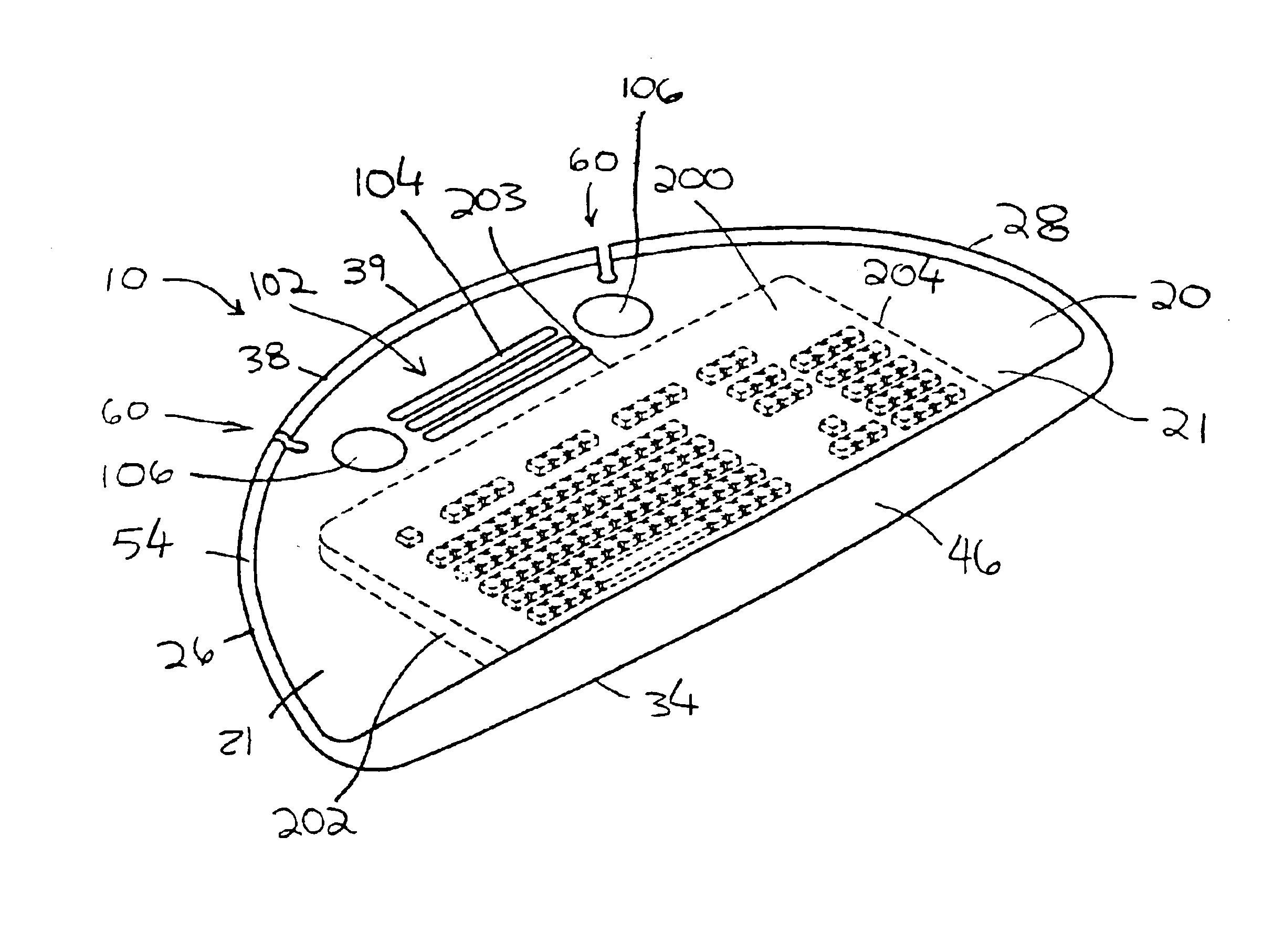
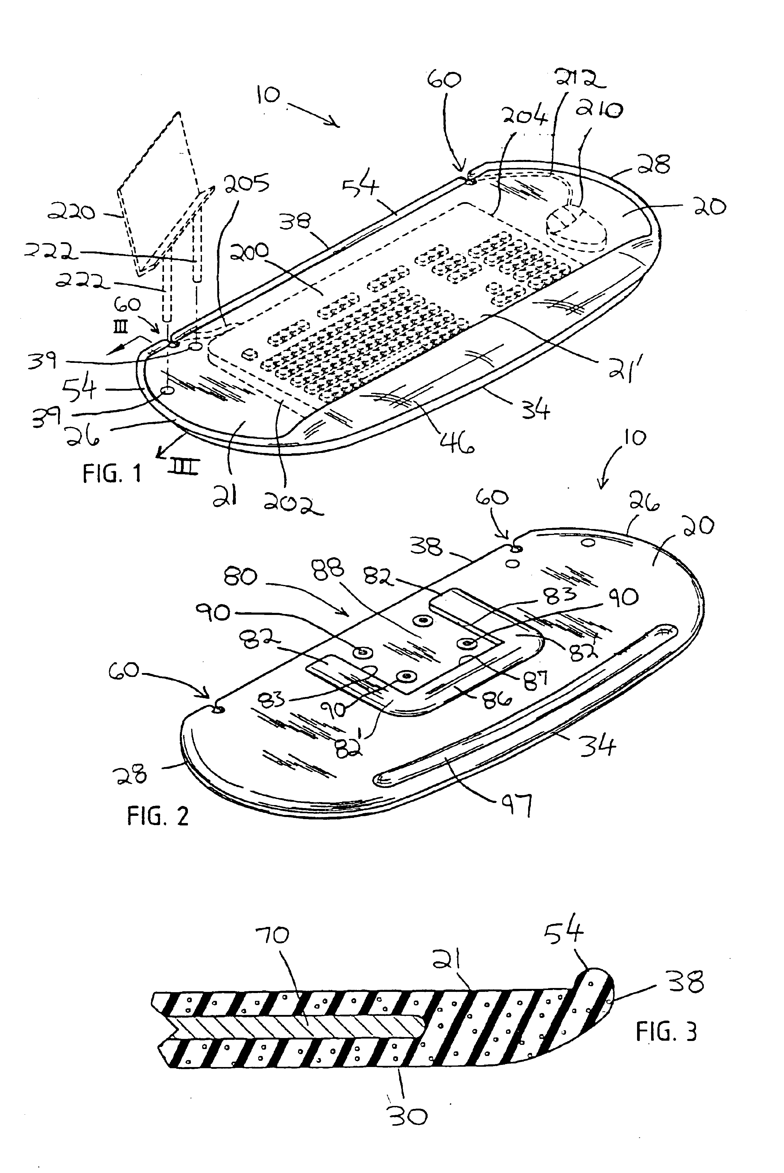
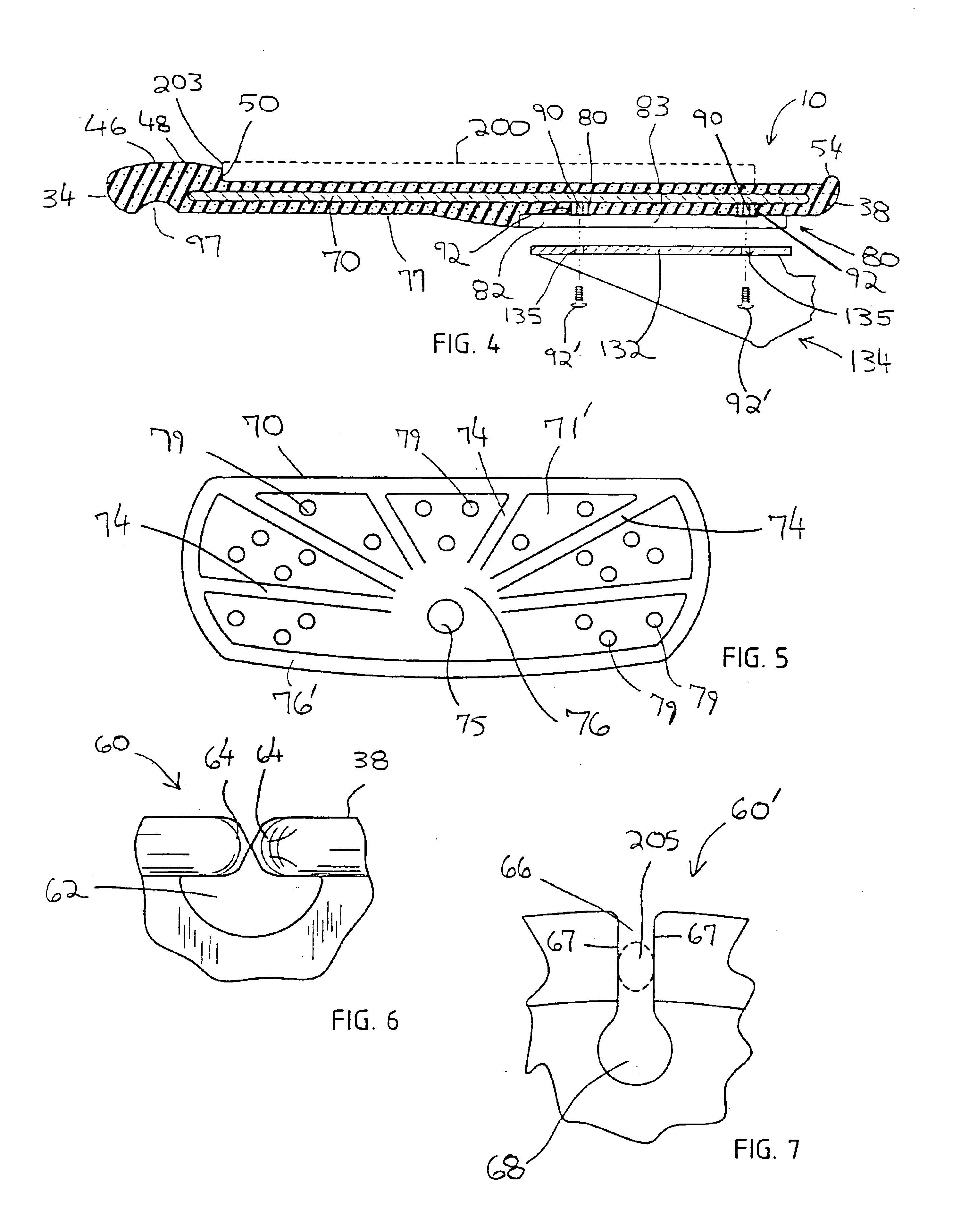
[0052]The present invention provides a keyboard tray and method for making the same, formed of a single polymeric material, and including a support member integrally molded within the interior of the keyboard tray. The support member of the present invention provides adequate rigidity and prevents the keyboard tray from flexing, enabling the keyboard tray to be used in conjunction with computer keyboard support mechanisms commonly used in both business and home environments. The keyboard tray of the present invention is economical to manufacture, and results in an aesthetically attractive device having sufficient cushioning to provide a comfortable typing surface and minimize the probability of contracting a repetitive stress injury.

[0053]Referring now to the FIG. 1 through 10, a computer keyboard tray 10, according to the present invention, includes a keyboard receiving member 20 having a top 21, a pair of opposing sides 26 and 28, a front 34, and a back 38. Sides 26 and 28, and fr...


PUM


Abstract

A computer keyboard tray includes a tray body formed from a compressible material and a support member, which provides reinforcement to the tray body. Optionally, the keyboard tray may incorporate an attachment assembly, allowing the keyboard tray to be removably attached to a computer keyboard support mechanism. Preferably, the keyboard tray includes a wrist rest which is monolithically formed with the tray body. In an alternative preferred embodiment, an adjustable wrist rest assembly is attached to the tray.

Description

CROSS REFERENCE TO RELATED APPLICATION[0001]This application is a continuation-in-part application of application Ser. No. 09 / 738,567, filed Dec. 15, 2001, now U.S. Pat. No. 6,644,605 which claims priority from U.S. Provisional Pat. Application Ser. No. 60 / 172,498, filed Dec. 17, 1999, the entire disclosure of which is hereby incorporated herein by reference.BACKGROUND OF THE INVENTION[0002]The present invention relates generally to devices for use in conjunction with a computer, and more particularly, to a polymeric computer keyboard tray and method for making the same.[0003]The use of computers in both business and the home is commonplace and routine. Our reliance upon personal computers continues to increase. A large number of individuals spend a majority of their day operating a personal computer. These individuals, as well as those having a pre-existing muscular or skeletal infirmity, are prone to the development of repetitive stress injuries. Repetitive stress injuries are mos...

Claims


Application Information

Patent Timeline
IPC IPC(8): A47B21/03A47B21/00
CPCA47B21/0314
Inventor TYNER, JEFF D.
Owner TYNER JEFF D
Learn More