Optical system for measuring metabolism in a body

Inactive Publication Date: 2005-06-07
HITACHI LTD +1
View PDF9 Cites 14 Cited by
  • Summary
  • Abstract
  • Description
  • Claims
  • Application Information

AI Technical Summary

Benefits of technology

[0013]If correction is made with respect to the sampling points arranged in the rhombic configuration thus obtained to form a tetra

Problems solved by technology

However, the optical topography systems and probes described above have the following problems.
Since the probes described above partially cover a head or cover the entire head by di

Method used


Image

  • Optical system for measuring metabolism in a body
  • Optical system for measuring metabolism in a body
  • Optical system for measuring metabolism in a body

Examples


Embodiment Construction

[0038]The embodiments of the present invention will be described herein below.

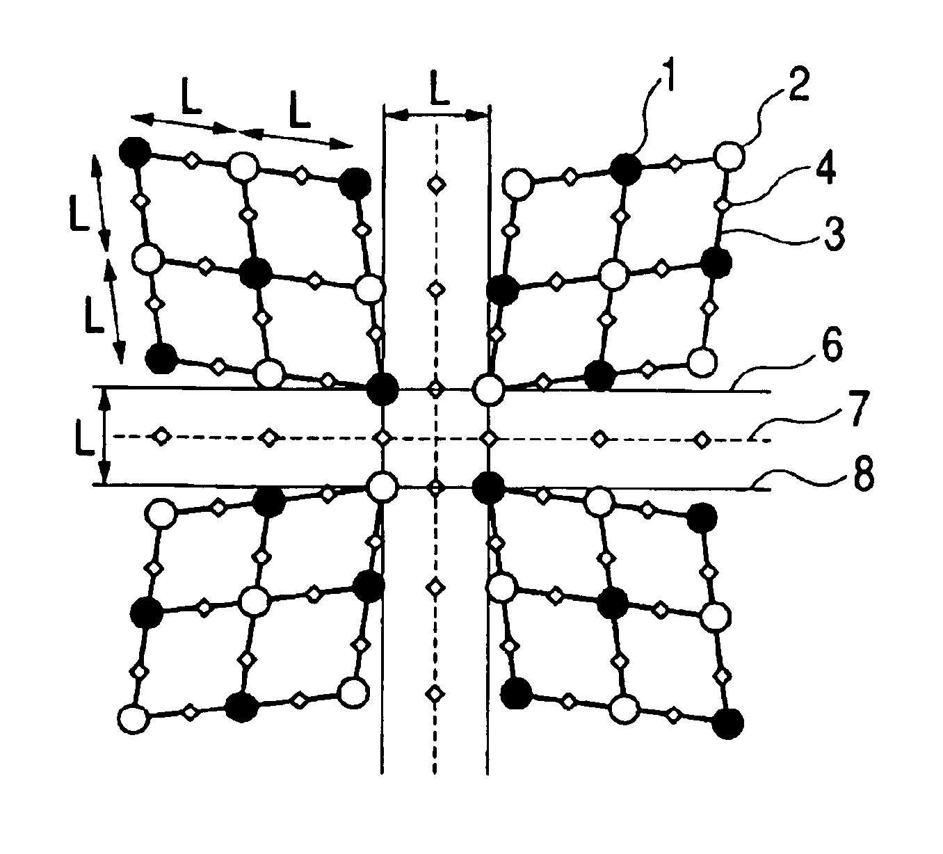
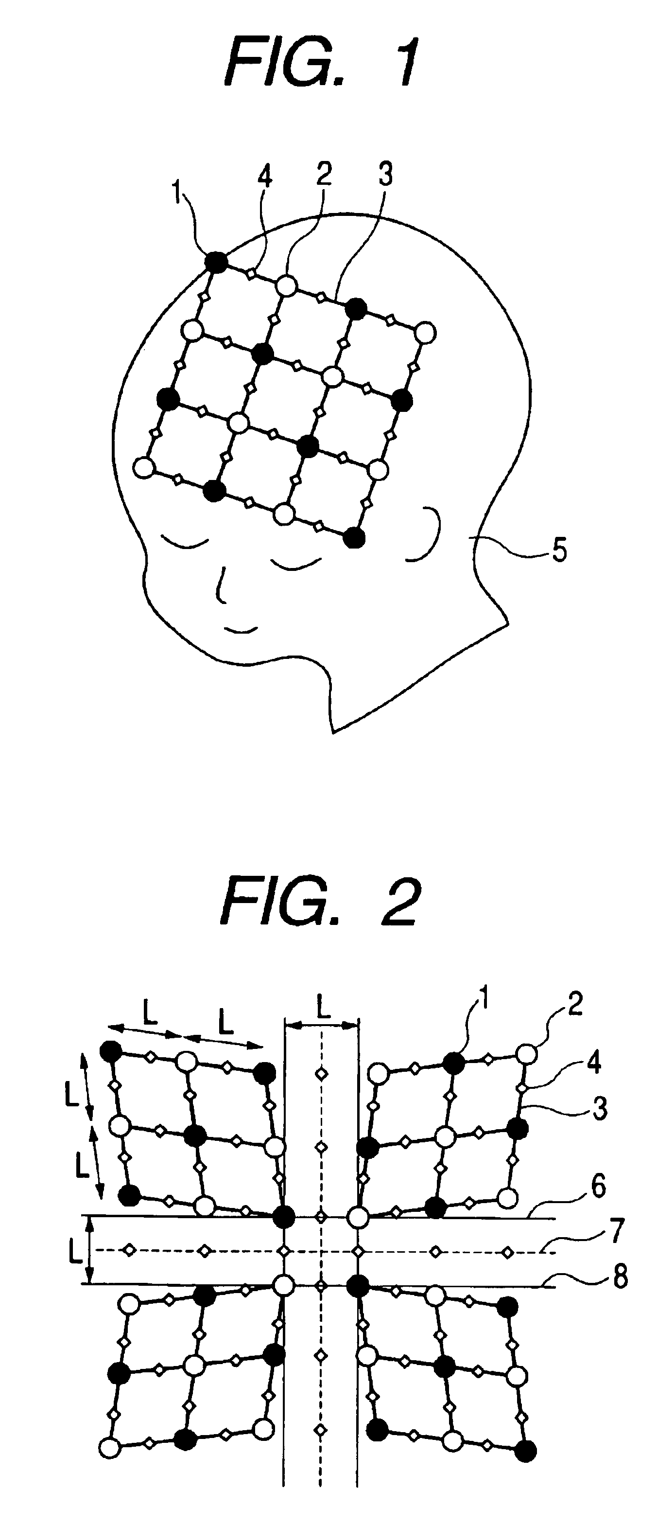
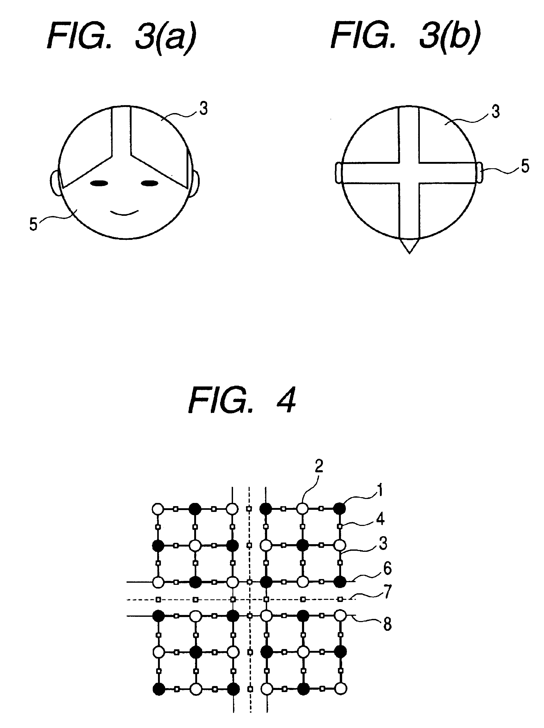
[0039]FIG. 1 is a view showing a conventional arrangement of probes. Irradiated points 1 and light receiving points 2 are arranged in nearly equi-spaced relation on a shell 3 configured as a tetragonal lattice. The shell 3 is attached to the head of a subject 5. Light for measurement emitted from a lamp, a light-emitting diode, a semiconductor laser, or the like passes through an optical fiber for incidence to be incident on the subject 5 from each of the irradiated points 1. The light propagated through a cerebral cortex portion in the head of the subject 5 passes through an optical fiber for detection attached to each of the light receiving points 2 to be transmitted to a light detector such as a photodiode or a photoelectron multiplier tube and detected. Since the intensity of the detected light fluctuates depending on the state of blood flows in the cerebral cortex, an increase and a decrease in the bl...


PUM


Abstract

Irradiated points and light receiving points are arranged such that sampling points are arranged over an entire spherical head with no vacant space. The sampling points are arranged to cover the entire spherical head by combining a plurality of rhombic shells and inverting the respective positions of irradiated points and light receiving points in the adjacent shells. As a result, a whole brain probe capable of covering the entire head is provided to allow an image of the whole brain to be viewed as a single image.

Description

FIELD OF THE INVENTION[0001]The present invention relates to an optical system for measuring, by using light, the concentration or variations in the concentration of a metabolite in a living body and more particularly, to a probe for measuring the concentration of a metabolite in a head.BACKGROUND OF THE INVENTION[0002]A technology (optical topography system) which measures variations in blood volume in a cerebral cortex with brain activity at multiple points and displays the variations in blood volume as a dynamic image or a static image has already been disclosed in Medical Physics, vol. 22, No. 12 pp. 1997-2005 (1995) (Atsushi Maki, Yuichi Yamashita, Yoshitoshi Ito, Eijyu Watanabe, Yoshiaki Mayanagi, and Hideki Koizumi, “Spatial and temporal analysis of human motor activity”), and in “Non-invasive measurement of language function by using optical topography”, Proceedings of SPIE, vol. 3597, pp. 230-237 (Tsuyoshi Yamamoto, Yuichi Yamashita, Hiroshi Yoshizawa, Atsushi Maki, Makoto ...

Claims


Application Information

Patent Timeline
IPC IPC(8): A61B5/026A61B5/00G01N21/17A61B5/145A61B5/1455
CPCA61B5/0059A61B5/0261A61B5/6814A61B2562/046A61B2562/0233
Inventor HIRABAYASHI, YUKIKOYAMAMOTO, TSUYOSHI
Owner HITACHI LTD
Why Eureka
Try Eureka