
Hydraulic coupling

Active Publication Date: 2005-06-14
HUCK PATENTS +1
View PDF13 Cites 33 Cited by
  • Summary
  • Abstract
  • Description
  • Claims
  • Application Information

AI Technical Summary

Benefits of technology

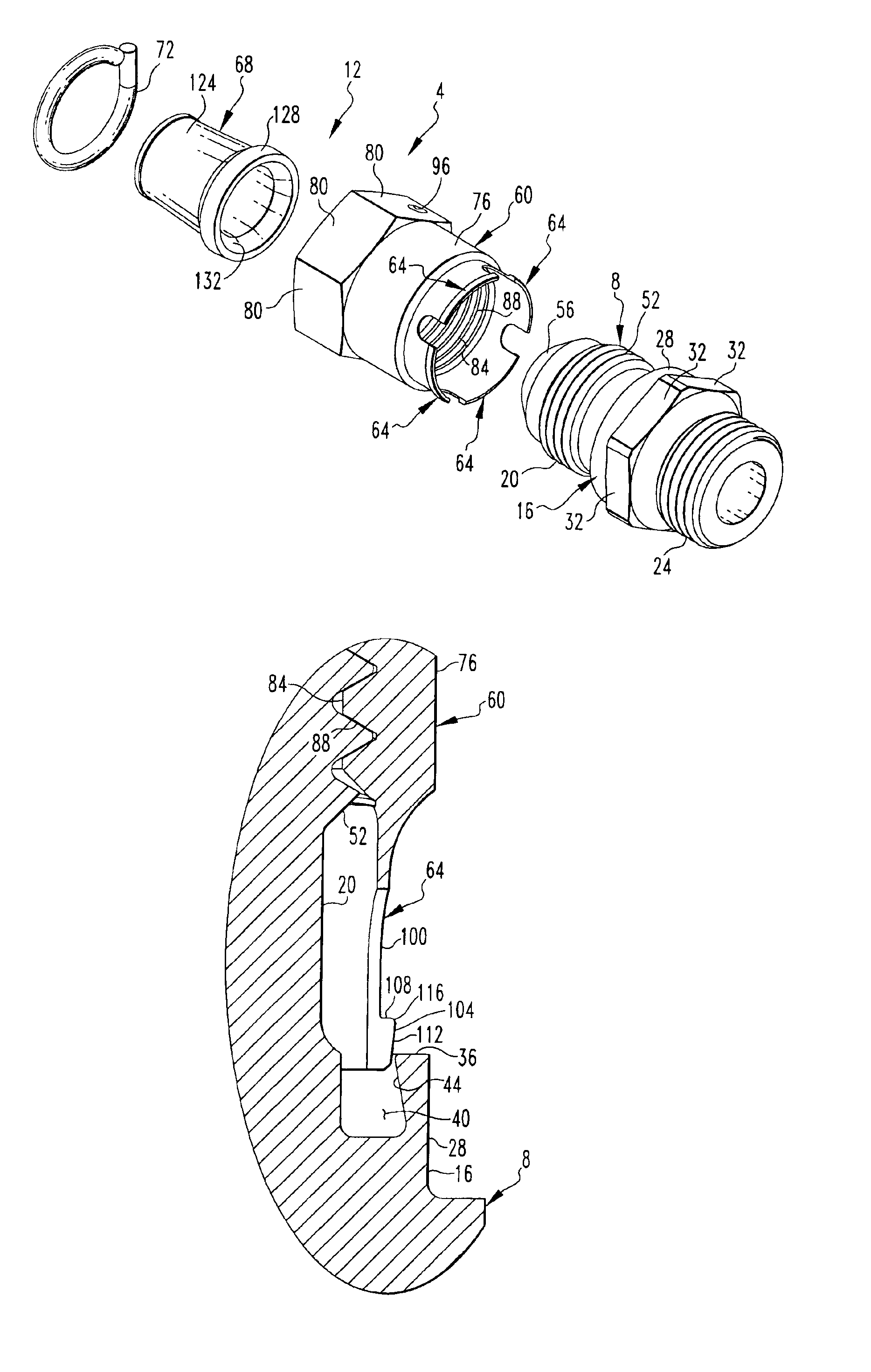
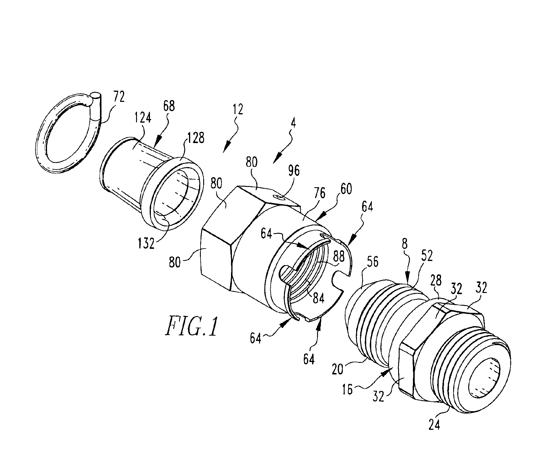
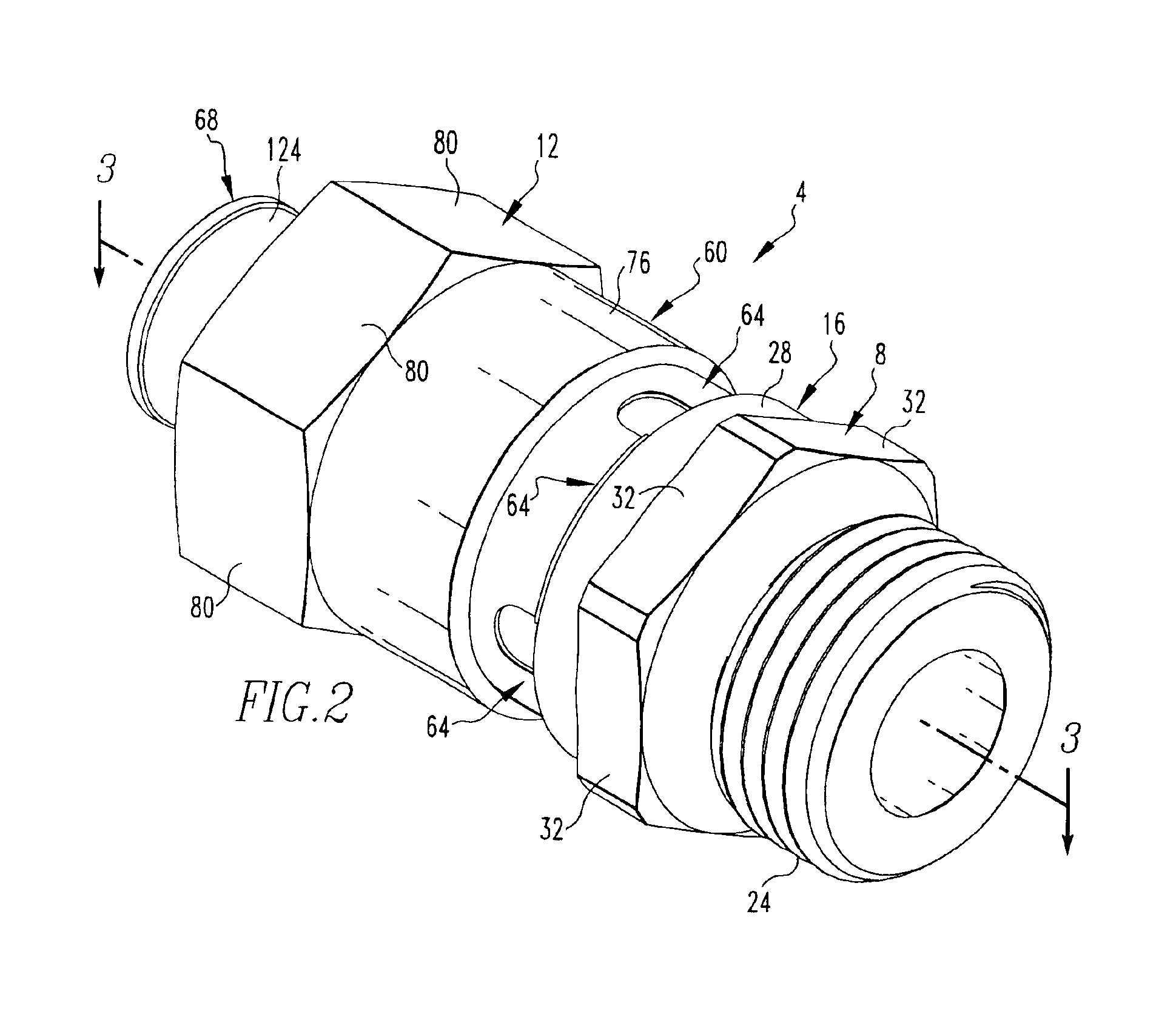
[0007]An improved hydraulic coupling in accordance with the present invention meets and exceeds these and other needs. An improved hydraulic coupling includes a fitting and a nut that are threadably connectable together. The fitting includes a generally annular groove having a lateral frusto-conic engagement surface. The nut includes a plurality of elongated fingers that each include a projection having an outwardly-disposed edge. When the coupling is assembled, the edges are frictionally engaged with the engagement surface as a result of the elastic deflection of the fingers. The frusto-conic shape of the engagement surface provides progressively greater frictional resistance in a direction of unthreading of the coupling, whereby loosening of the coupling during operation of the fluid circuit is resisted.
[0008]Accordingly, an aspect of the present invention is to provide an improved coupling that provides a substantially leak-free seal between components of a fluid circuit.
[0009]Another aspect of the present invention is to provide an improved coupling that resists loosening in an environment of elevated and varying temperatures, pressures, and vibration.
[0010]Another aspect of the present invention is to provide an improved coupling having a plurality of fingers with protrusions that are frictionally engaged with a frusto-conic surface of another structure to provide progressively increasing frictional resistance in an unthreading direction.

Problems solved by technology

The high vibration environment of a hydraulic circuit, combined with the expansions and contractions of the components of a hydraulic circuit resulting from temperature changes and high pressures, causes the threaded portions of hydraulic fittings to gradually loosen, i.e., unthread, over time.
Generally any loosening of a coupling will result in a leakage of the fluid from within the circuit, and progressively greater degrees of loosening typically cause progressively greater rates of fluid loss.

Method used


Image

  • Hydraulic coupling
  • Hydraulic coupling
  • Hydraulic coupling

Examples


Embodiment Construction

[0019]An improved coupling 4 in accordance with the present invention is indicated generally in FIGS. 1-5. The coupling 4 is advantageously configured to provide a substantially leak-free seal between various components of a hydraulic circuit and to resists loosening in the presence of elevated and changing temperatures, pressures and vibration. While the exemplary fluid circuit described herein is a hydraulic circuit, it is noted that the coupling 4 can be employed in other fluid circuits, whether or not the fluid circuits are closed or open, i.e., whether or not they are continuous. The coupling 4 of the present invention advantageously includes a self-locking feature that resists loosening during use in its intended environment, as will be described in greater detail below.

[0020]In the broadest sense, the coupling 4 can be considered to include a fitting 8 and a nut 12. The fitting 8 and the nut 12 are threadably connectable together pursuant to the formation of the substantially...


PUM


Abstract

An improved hydraulic coupling includes a fitting and a nut that are threadably connectable together. The fitting includes a generally annular groove having a lateral frusto-conic engagement surface. The nut includes a plurality of elongated fingers that each include a projection having an outwardly-disposed edge. When the coupling is assembled, the edges are frictionally engaged with the engagement surface as a result of the elastic deflection of the fingers. The frusto-conic shape of the engagement surface provides progressively greater frictional resistance in a direction of unthreading of the coupling, whereby loosening of the coupling during operation of the fluid circuit is resisted.

Description

CROSS-REFERENCE TO RELATED APPLICATION[0001]The present application claims priority from U.S. Provisional Patent Application Ser. No. 60 / 413,345 filed Sep. 25, 2002, the disclosures of which are incorporated herein by reference.FIELD OF THE INVENTION[0002]The present invention relates generally to hydraulic fittings and, more particularly, to a self-locking hydraulic fitting.BACKGROUND OF THE INVENTION[0003]Various types of fluid couplings are employed in fluid circuits. Such fluid couplings are typically employed to connect together separate components of a fluid system, such as when a first tube is connected together with a second tube or with another structure such as a manifold block. Such fluid couplings generally are designed to provide substantially leak-free seals between connected components in a given environment.[0004]Fluid couplings often include components that are tightly threaded together to provide the substantially leak-free seal. The threaded configuration of the c...

Claims


Application Information

Patent Timeline
IPC IPC(8): F16L19/00F16L19/03
CPCF16L19/005
Inventor DO, TAILE, TUNG N.LOZANO, LUIS F.
Owner HUCK PATENTS
Learn More