Electrical device

a technology of electric devices and adhesive layers, applied in the direction of coupling device connections, electrical apparatus casings/cabinets/drawers, semiconductor/solid-state device details, etc., can solve the problems of increasing heat dissipation, increasing costs, and increasing costs, and achieves the effect of simplifying the application of the insulating and adhesive layer

Inactive Publication Date: 2005-06-14
SIEMENS AG
View PDF2 Cites 4 Cited by
  • Summary
  • Abstract
  • Description
  • Claims
  • Application Information

AI Technical Summary

Benefits of technology

[0003]The object of the present invention is to permit and / or improve the dissipation of the lost heat in circuits of this type with low costs.
[0008]Simple and dependable contacting of the circuit with the leadframe is made possible in the case of another advantageous refinement of the device according to the invention by the leadframe taking up a larger surface area than the support plate and by leads of the leadframe which are intended for the circuit arranged on the support plate protruding as contact areas above the plane of the leadframe alongside the support plate.
[0009]An advantageous development of the device according to the invention consists in that the further electrical components are arranged in a housing, with electrical contact elements pointing in the direction of an open side of the housing and being connected to contact areas of the leadframe, that the plastic-encapsulated leadframe substantially takes up the open side of the housing, with the circuit arranged on the support plate facing outward, and that the housing can be closed by a cover which is designed for receiving at least the circuit. In the case of this development, simple assembly of the device and dependable mounting and fixing of the plastic-encapsulated leadframe are possible.
[0010]In the case of this development, it is preferably provided that the surface area of the leadframe intended for the heat conduction protrudes beyond the edge of the housing. This measure simplifies the application of the insulating and adhesive layer in series production. For example, a screen printing tool can easily be brought up to the surface area of the leadframe to be printed on, without the edge of the housing being disturbed or unintentionally printed on.

Problems solved by technology

In spite of lower power loss, these circuits require measures for dissipating the lost heat, which involves additional, often considerable expenditure.
This heat dissipation is often hampered still further by the fact that the devices are arranged in closed housings.

Method used


Image

  • Electrical device
  • Electrical device
  • Electrical device

Examples


Embodiment Construction

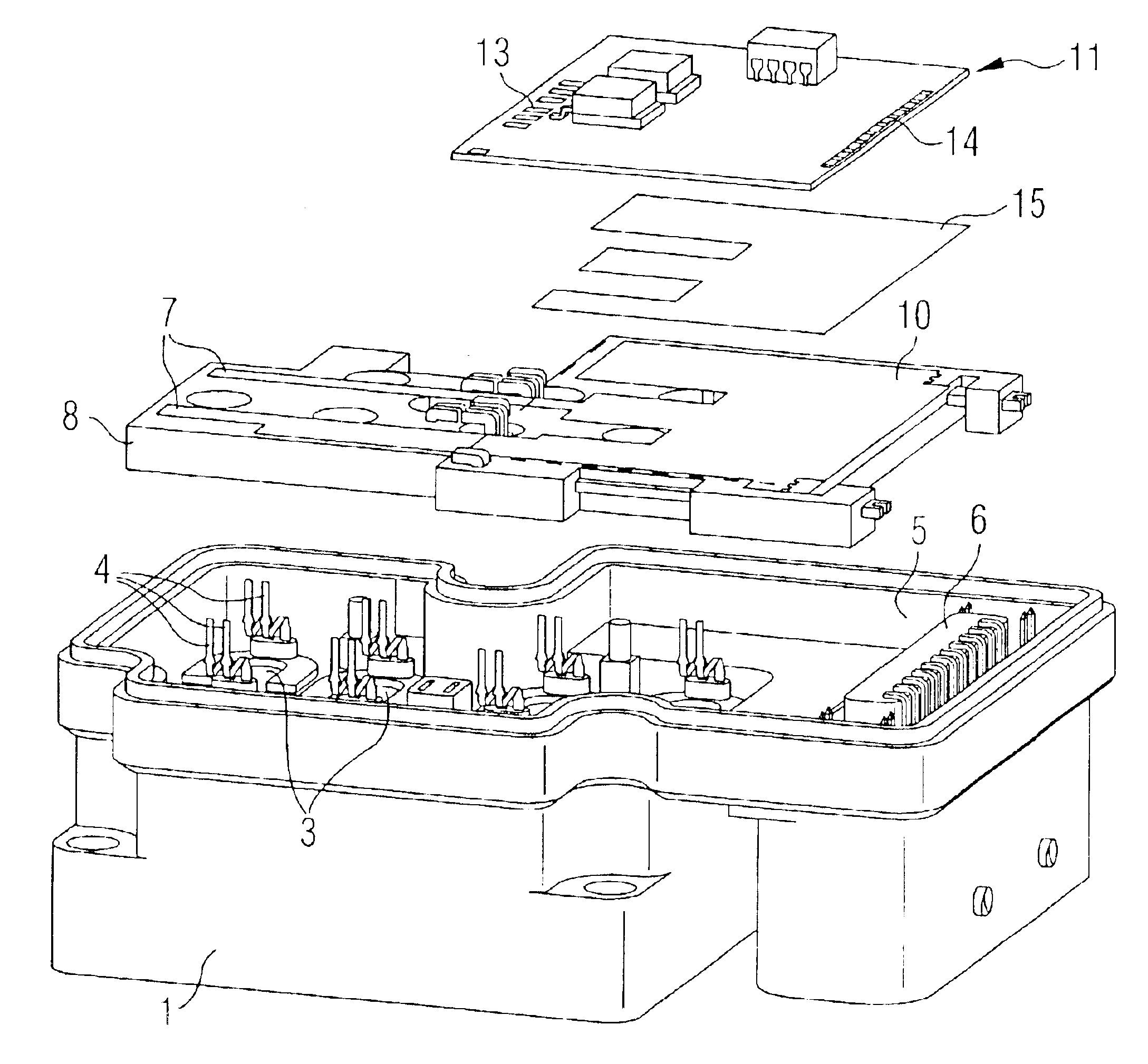
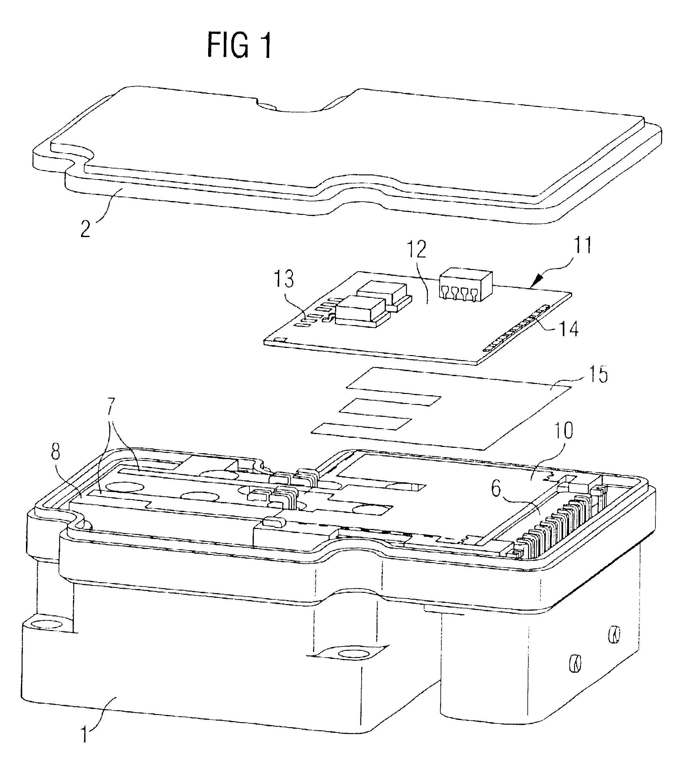
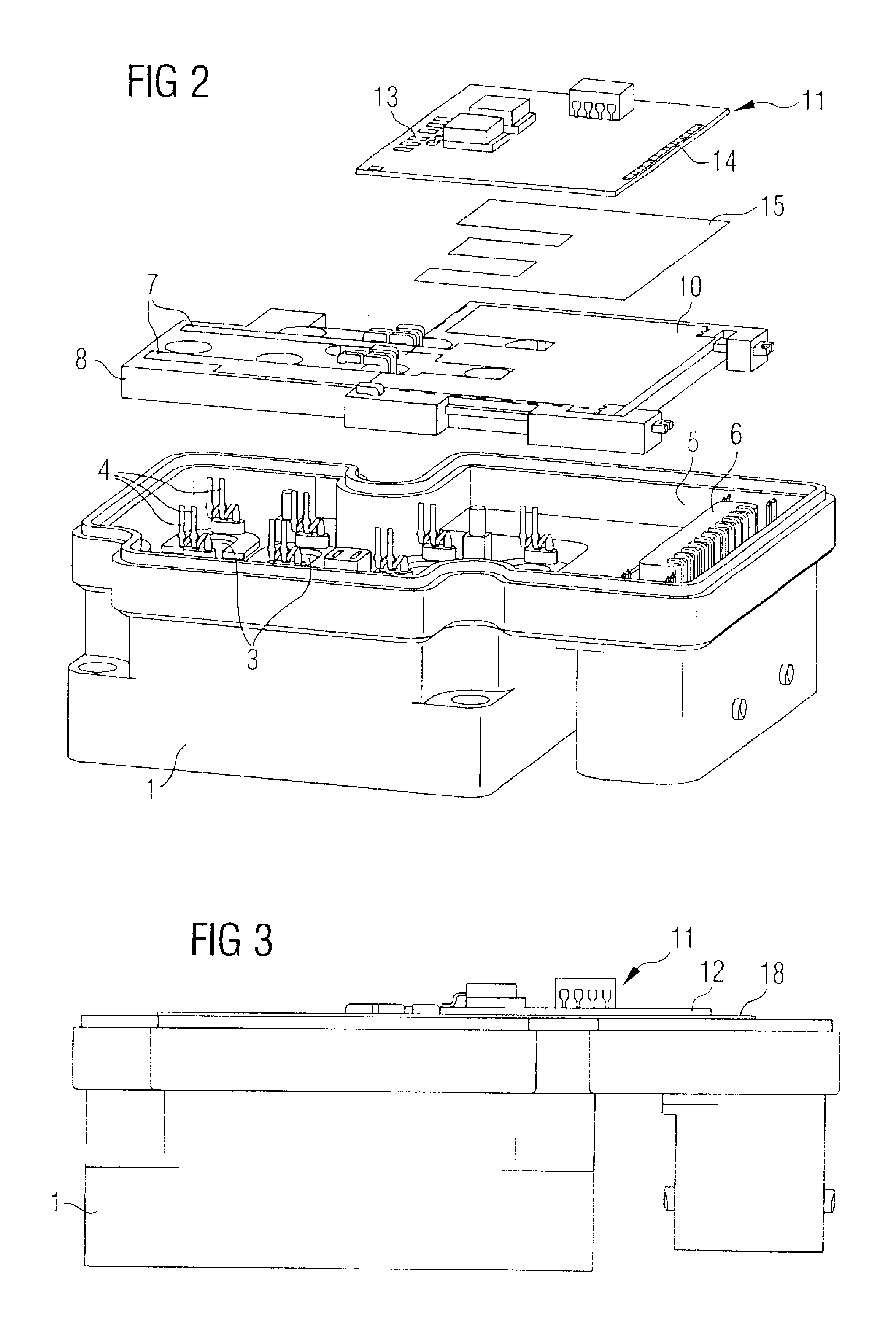
[0019]The figures show a device according to the invention in a practical configuration, presenting a series of details which are not significant in connection with the invention and are therefore not described in any more detail. The same parts are provided in the figures with the same reference numerals.

[0020]The device represented comprises a housing 1 and a cover 2. Arranged in the housing are various electrical components 3, the terminal pins 4 of which point in the direction of the opening 5 of the housing 1. The housing also contains a plug-in connector 6. The leadframe 7 is encapsulated in plastic 8, so that it forms a stable component which can be fitted into the housing in such a way that welding lugs 9 of the leadframe 7 can be connected to the terminal pins 4 of the components 3. A part 10 of the leadframe 7 is formed with a flat surface area and serves for receiving a circuit 11 with a support plate 12, various components, which are only indicated, and contact areas 13,...


PUM


Abstract

With an electrical device with a circuit arranged on a support plate and with a leadframe, forming electrical leads, for the electrical connection of the circuit to further electrical components, the support plate is in heat-conducting connection with at least a part of the leadframe. The leadframe may be formed at least partly with a flat surface area and the support plate may rest on the flat part. An electrical insulation between the support plate and the leadframe may be formed by a double-sided adhesive film or by a printed-on adhesive.

Description

FIELD AND BACKGROUND OF THE INVENTION[0001]The invention relates to an electrical device with a circuit arranged on a support plate and with a leadframe, forming electrical leads, for the electrical connection of the circuit to further electrical components.[0002]In electrical devices, for example control devices for motor vehicles, so-called leadframes, which interconnect the corresponding components, such as coils and high-power semiconductor devices, are often used for conducting relatively high currents. More complex circuits of lower power are in this case respectively configured as hybrid circuits or by printed circuit technology on a support plate. In spite of lower power loss, these circuits require measures for dissipating the lost heat, which involves additional, often considerable expenditure. This heat dissipation is often hampered still further by the fact that the devices are arranged in closed housings.SUMMARY OF THE INVENTION[0003]The object of the present invention ...

Claims


Application Information

Patent Timeline
Patent Type & Authority Patents(United States)
IPC IPC(8): H05K5/00H05K7/20H05K3/00H05K1/02H01L23/12H01L23/36
CPCH05K7/20854H05K1/0203H05K3/0058H01L2924/0002H01L2924/00H05K1/02
Inventor DORRHOFER, STEFANSCHULTZ, DIETMARNITZSCHKE, MICHAEL
Owner SIEMENS AG
Why Eureka
Try Eureka