Modular coaxial electrical interconnect system having a modular frame and electrically shielded signal paths and a method of making the same

a coaxial electrical interconnection and modular frame technology, applied in the direction of coupling device connection, electrical apparatus, coupling protective earth/shielding arrangement, etc., can solve the problems of reducing the effective density of the connector, high-speed signals that are transferred through such interconnections are susceptible to cross talk, etc., to achieve efficient utilization of space and increase signal speed

Inactive Publication Date: 2005-06-14
SILICON BANDWIDTH
View PDF64 Cites 105 Cited by
  • Summary
  • Abstract
  • Description
  • Claims
  • Application Information

AI Technical Summary

Benefits of technology

[0011]An advantage of the present invention is to provide increased signal speed through the use of coaxial contacts assembled as a series of modules.
[0012]Another advantage of the present invention is to provide more efficient utilization of the space on the printed wiring board to which the connector is attached due to the density achieved.
[0013]Additional features and advantages of the invention will be set forth in the description which follows, and in part will be apparent from the description, or may be learned by practice of the invention. The objectives and other advantages of the invention will be realized and attained by the structure particularly pointed out in the written description and claims hereof as well as the appended drawings.
[0014]To achieve these and other advantages and in accordance with the purpose of the present invention, as embodied and broadly described, a modular connector assembly may include a modular frame having a first surface and a second surface connected at an angle to each other at a first angle region. The first surface, second surface, and the first angle region include first holes, second holes, and third holes, respectively, that are formed at evenly spaced intervals. Modular interconnect components, fixable within the modular

Problems solved by technology

The high speed signals that are transferred through such interconnections are susceptible to cross talk due to the signal speeds and proximate locations of the signal carrying conductors adja

Method used


Image

  • Modular coaxial electrical interconnect system having a modular frame and electrically shielded signal paths and a method of making the same
  • Modular coaxial electrical interconnect system having a modular frame and electrically shielded signal paths and a method of making the same
  • Modular coaxial electrical interconnect system having a modular frame and electrically shielded signal paths and a method of making the same

Examples


Embodiment Construction

[0030]Reference will now be made in detail to an embodiment of the present invention, example of which is illustrated in the accompanying drawings.

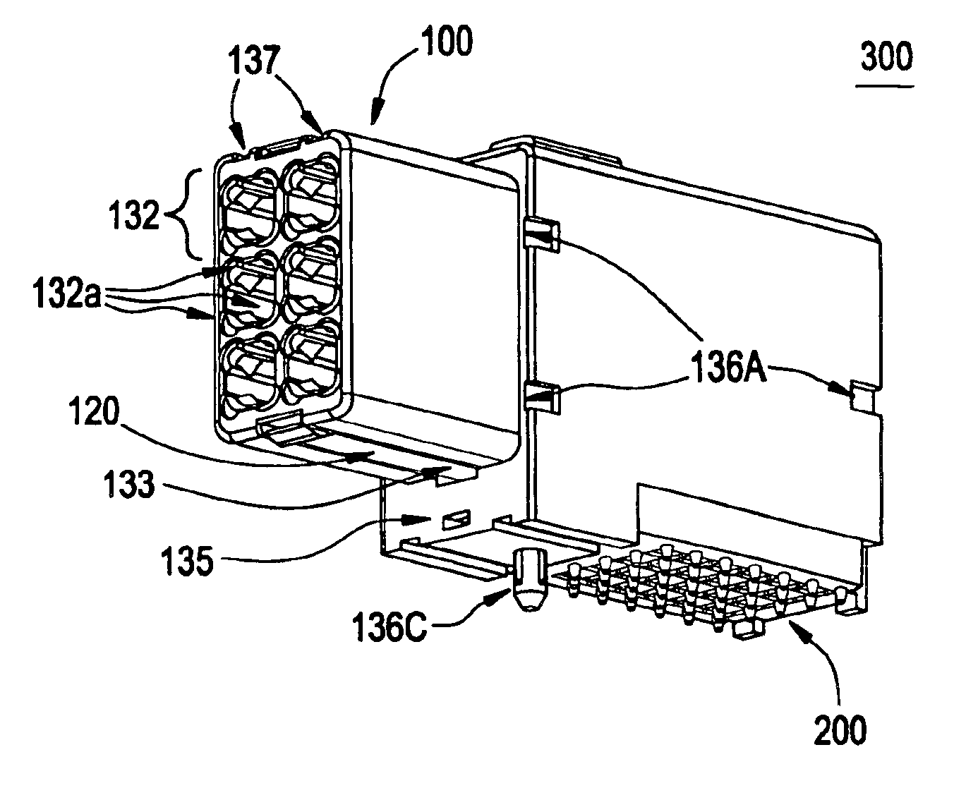
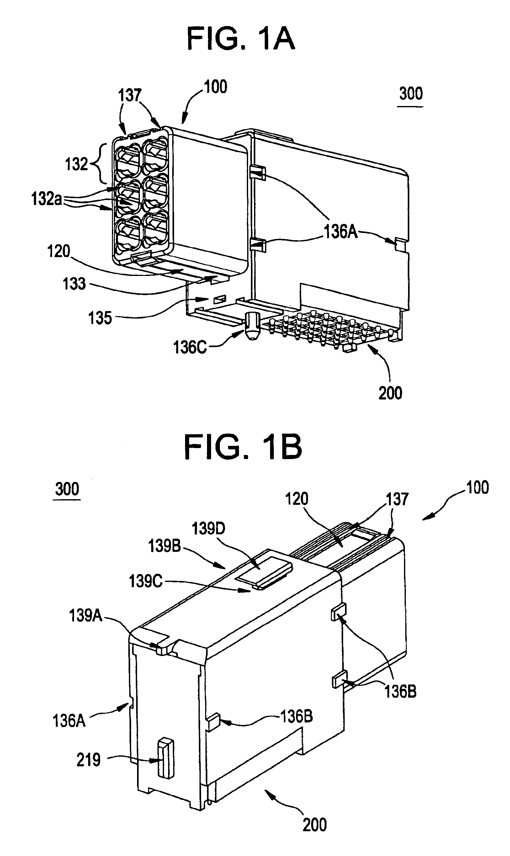
[0031]Referring to FIGS. 1A and 1B, front and back views, respectively, are provided of a modular female interconnect component 300 comprising coaxial reception type connections according to the principles of the present invention generally comprises a female unit 100 electrically and mechanically connected to a female right angle unit 200.

[0032]Referring to FIGS. 3 and 4A-4F, an exploded view of the female unit 100 of the modular female interconnect component 300 shown in FIGS. 1A and 1B and perspective views of its individual components offers a detailed description of the female unit and its manufacture.

[0033]Referring to FIG. 4A, a female contact housing 130 comprises a unitary molded piece made of liquid crystal polymer (LCP) or other suitable electrically insulating material which exhibits little or no shrinkage during the molding p...


PUM


Abstract

A modular connector assembly includes a modular frame having a first holes, second holes, and third holes formed at evenly spaced intervals. A plurality of modular interconnect components, fixable within the modular frame, have a back surface projection formed thereon. Each modular interconnect includes a contact housing made of electrically insulating material, an exterior of the contact housing comprising first and second side surfaces, a back surface, and a top surface. Contact signal pins are fixed within and electrically insulated from the contact housing.

Description

BACKGROUND OF THE INVENTION[0001]1. Field of the Invention[0002]The present invention relates in general to electrical connectors. More particularly, the present invention relates to a connector assembly for use in coaxial connection with circuit boards. Even more particularly, this invention relates to electrical connectors having densely packed contact members capable of passing signals while minimizing cross talk between adjacent contact members and increasing electrical efficiencies, especially at high frequencies.[0003]2. Discussion of the Related Art[0004]Electrical interconnect systems (including electronic interconnect systems) are used for interconnecting electrical and electronic systems and components. In general, electrical interconnect systems include both a male interconnect component, such as a conductive pin, and a female interconnect component, such as a conductive socket. In these types of electrical interconnect systems, electrical interconnection is accomplished ...

Claims


Application Information

Patent Timeline
IPC IPC(8): H01R13/518H01R13/514H01R13/516
CPCH01R13/514H01R13/518H01R12/727
Inventor CRANE, JR., STANFORD W.JEON, MYOUNG-SOONICKEL, JOSH
Owner SILICON BANDWIDTH
Why Eureka
Try Eureka