Closed-loop control of electrokinetic processes in microfluidic devices based on optical readings

a microfluidic device and closed-loop control technology, applied in fluid pressure measurement, liquid/fluent solid measurement, peptide measurement, etc., can solve the problems of inconvenient timing of voltage application, and inconvenient visualization of dye concentration

Active Publication Date: 2005-06-14
MONOGRAM BIOSCIENCES
View PDF10 Cites 104 Cited by
  • Summary
  • Abstract
  • Description
  • Claims
  • Application Information

AI Technical Summary

Benefits of technology

[0030]FIGS. 4a-4b show separation results of a sample separated on a microfluidic device using a closed-loop control ITP / zone electrophoresis process.
[0031]FIG. 5 shows results of multiple separations using a closed-loop control process.

Problems solved by technology

However, accurately timing the application of voltages is fraught with difficulty since the timing depends on, amongst other things, the sample to be assayed.
This is impractical.
Visualizing dye concentrations is also undesirable.
Visualization of dye concentrations is undesirable because it is based on operator (human) observation.
Human observation may be inaccurate and vary with time.
Over long periods of time, for example, the observer's senses may deteriorate due to fatigue.

Method used


Image

  • Closed-loop control of electrokinetic processes in microfluidic devices based on optical readings
  • Closed-loop control of electrokinetic processes in microfluidic devices based on optical readings
  • Closed-loop control of electrokinetic processes in microfluidic devices based on optical readings

Examples


example

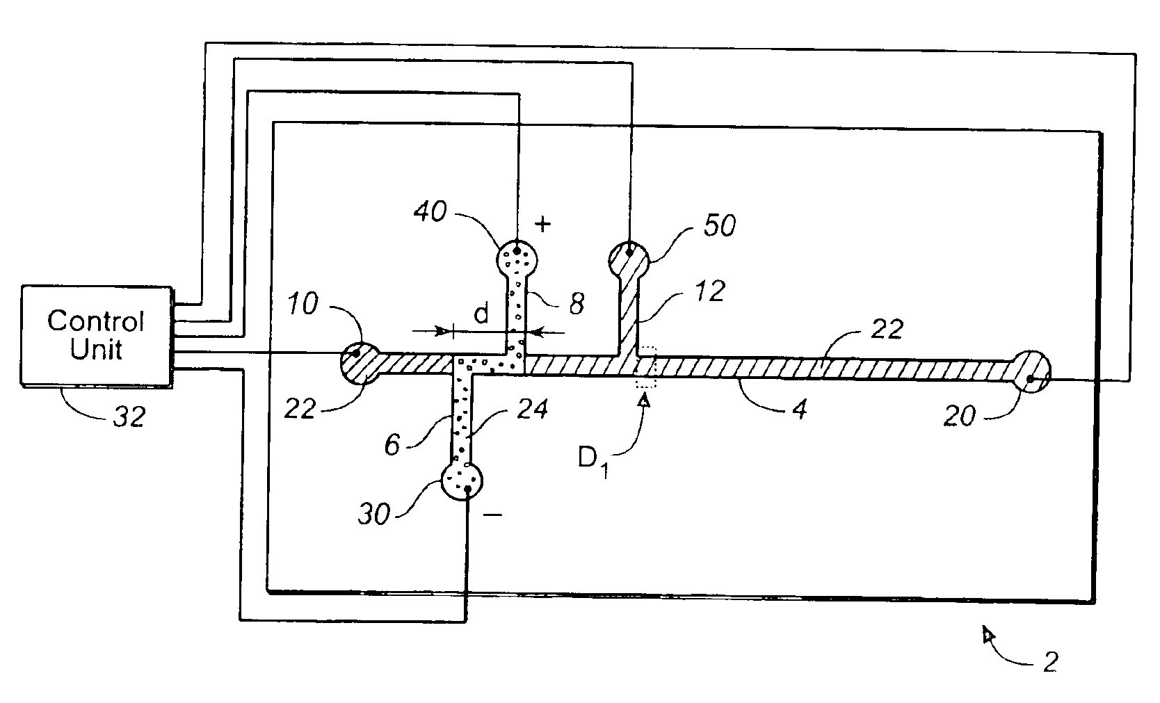
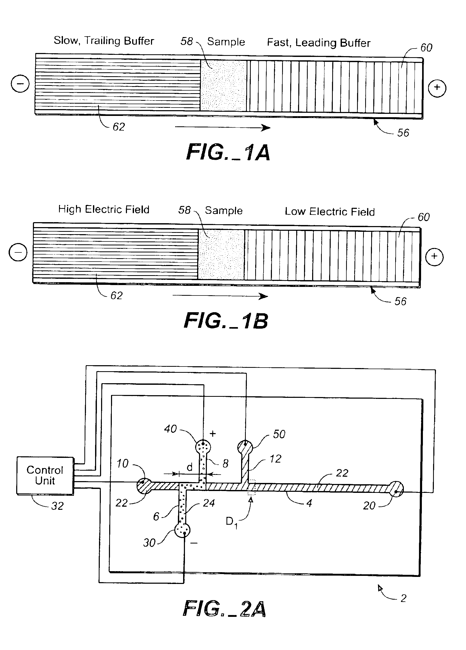
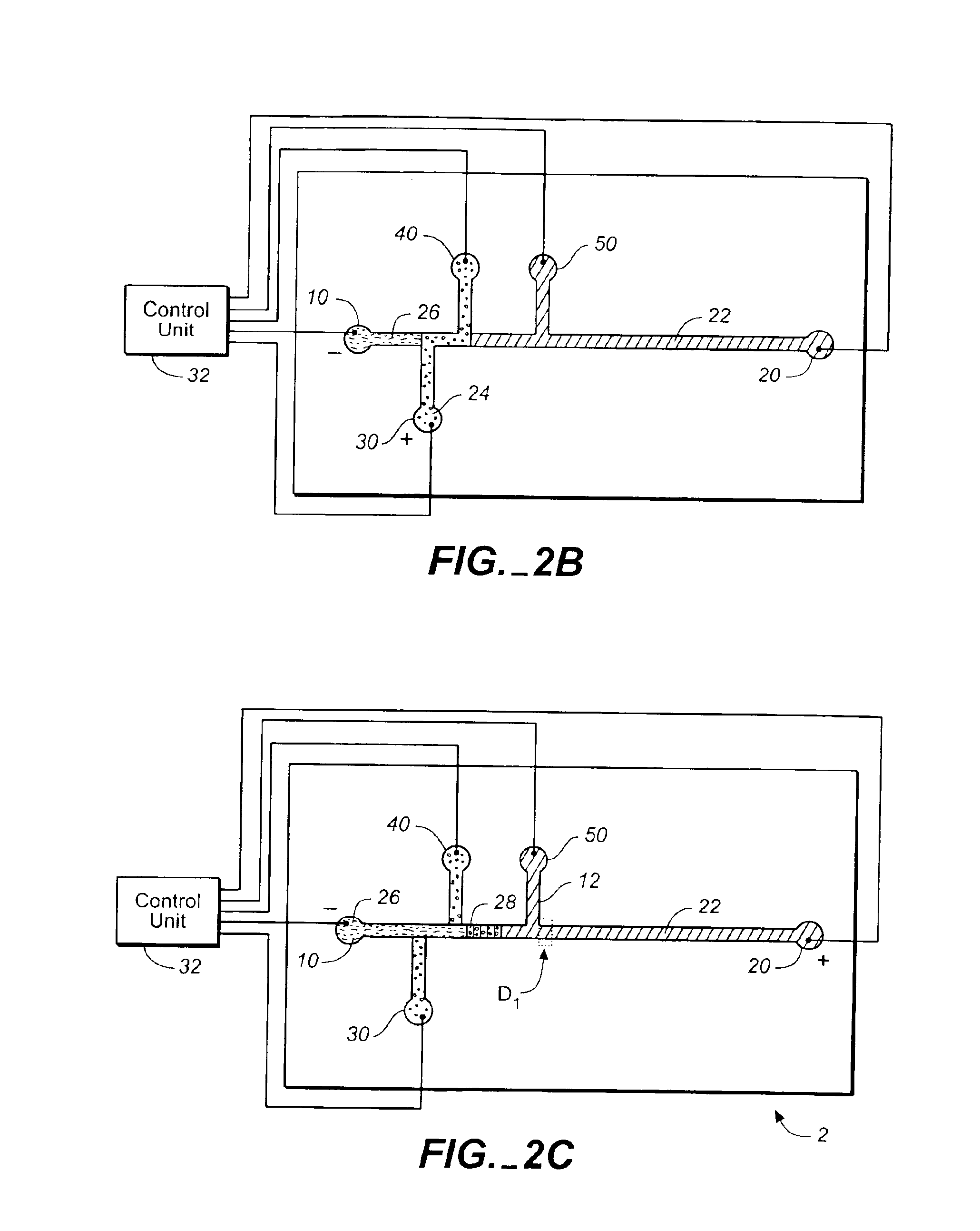
[0068]An ITP zone separation was performed on a microfluidic device using a closed-loop controller that automatically switched the voltages upon sensing a portion of a sample. The device was configured as shown in FIGS. 2A-2E.

[0069]A sample containing twelve different electrophoretic tag (eTag) reporters, each labeled with fluorescein, was added to the device and concentrated (or ITP stacked) as described in the text, above, corresponding to FIGS. 2A-2C. The concentrated sample was electrokinetically driven to detection point D1.

[0070]Detection point D1 was monitored using a photomultiplier tube (PMT) detector. The PMT detector collected the signal generated by laser induced fluorescence. An argon laser was directed at the detection point. The excitation wavelength was 488 nm. Emission was collected at 515-540 nm.

[0071]When the sample reached detector (D1), and the PMT detector recorded a large signal indicating that the sample had reached this detection point, the controller automa...


PUM

PropertyMeasurementUnit
anglesaaaaaaaaaa
thicknessaaaaaaaaaa
thicknessaaaaaaaaaa

Abstract

A method for performing an electrophoretic separation on a microfluidic device includes applying an electric field to electrokinetically move a sample along a channel towards a location. The sample may be concentrated by application of the electric field. The method further comprises optically monitoring the location for at least a portion of the sample. Once the sample is detected, the electric field is automatically changed to further manipulate the sample. The sample may be spatially separated along a separation channel or channel portion. The closed-loop control of electric fields may be performed using a control unit adapted to apply a voltage potential between electrodes and an optical detector such as an LIF detector.

Description

CROSS-REFERENCE TO RELATED APPLICATIONS AND PATENTS[0001]This application claims priority from U.S. provisional applications Ser. No. 60 / 433,183, filed 13 Dec. 2002, which application is incorporated herein by reference in its entiretyFIELD OF THE INVENTION[0002]The present invention is directed to electrokinetic processes performed on microfluidic devices and in particular, to automatically controlling electric fields used in carrying out electrophoretic separations.BACKGROUND ART[0003]Microfluidics is revolutionizing the way activities are performed in a substantial proportion of chemical and physical operations. One area of microfluidics is the manipulation of small volumes of liquids or liquid compositions on a solid substrate, where a network of channels and reservoirs are present. By employing electric fields with electrically conducting liquids, volumes and / or ions can be moved from one site to another, different solutions formed by mixing liquids and / or ions, reactions perfo...

Claims


Application Information

Patent Timeline
Patent Type & Authority Patents(United States)
IPC IPC(8): G01N27/447G01L1/20C08F2/58
CPCG01N27/44773G01N27/44721
Inventor WAINRIGHT, ANNBJORNSON, TORLEIF
Owner MONOGRAM BIOSCIENCES
Why Eureka
Try Eureka