Power supply controller for exercise equipment drive motor

a technology of power supply controller and drive motor, which is applied in the direction of electric variable regulation, process and machine control, instruments, etc., can solve the problems of reducing the efficiency of the passive circuit, so as to improve the power factor and improve the transfer of heat. , the effect of improving the power factor

Inactive Publication Date: 2005-06-14
PRECOR
View PDF4 Cites 105 Cited by
  • Summary
  • Abstract
  • Description
  • Claims
  • Application Information

AI Technical Summary

Benefits of technology

[0020]Further embodiments of the present invention may provide an intelligent control module that includes control circuitry for controlling the opening and closing of the switching device that modulates the current received from the power source. The control circuitry may be comprised of a digital processor that operates in accordance with instructions stored in a memory. By modulating the current received from the power source, the control circuitry may achieve an improved power factor in the control module. Power factor may be improved by modulating the input current to be closer in phase with the voltage of the input power source.
[0021]In still further embodiments, a single heat sink may be connected to the control module and configured to provide cooling for the entire module. A fan may also be included with the heat sink to improve the transfer of heat from the control module.

Problems solved by technology

The large peak to average ratio of the current also produces losses in the circuit, such as heating.
These components do not contribute to the usable power received by the load.
While a passive circuit is generally less complicated and less expensive to build than an active circuit, it is difficult to optimize a passive circuit for universal line operation.
Each of the integrated circuits has its own limitations and operating characteristics.
Because of this, prior art PFC circuits are generally designed for a narrow range of input and output power and cannot handle power conversion over a wide range.
Expanding the range of power that conventional PFC circuits can handle and still maintaining a constant power output is very expensive and difficult to implement.
The prior art is also limited in that conventional PFC circuits are implemented separately from other power circuits.
Having a PFC circuit and an inverter implemented separately on different circuit boards, as done in the prior art, increases the complexity of the overall motor control circuit, is more susceptible to electrical noise, and is more difficult to cool, usually resulting in increased cost and size of the circuitry.

Method used


Image

  • Power supply controller for exercise equipment drive motor
  • Power supply controller for exercise equipment drive motor
  • Power supply controller for exercise equipment drive motor

Examples


Embodiment Construction

[0045]The invention described herein is directed to a circuit for controlling a power supply that delivers electrical power to a load and is particularly suited for powering AC or DC motors in exercise equipment. While certain circuits of the present invention have a primary application in powering exercise equipment, it will be appreciated that circuits constructed according to the present invention may be used in other applications where electrical power is supplied to a load. Thus, specific descriptions of the invention relating to powering AC or DC motors for use with exercise equipment are intended to be illustrative.

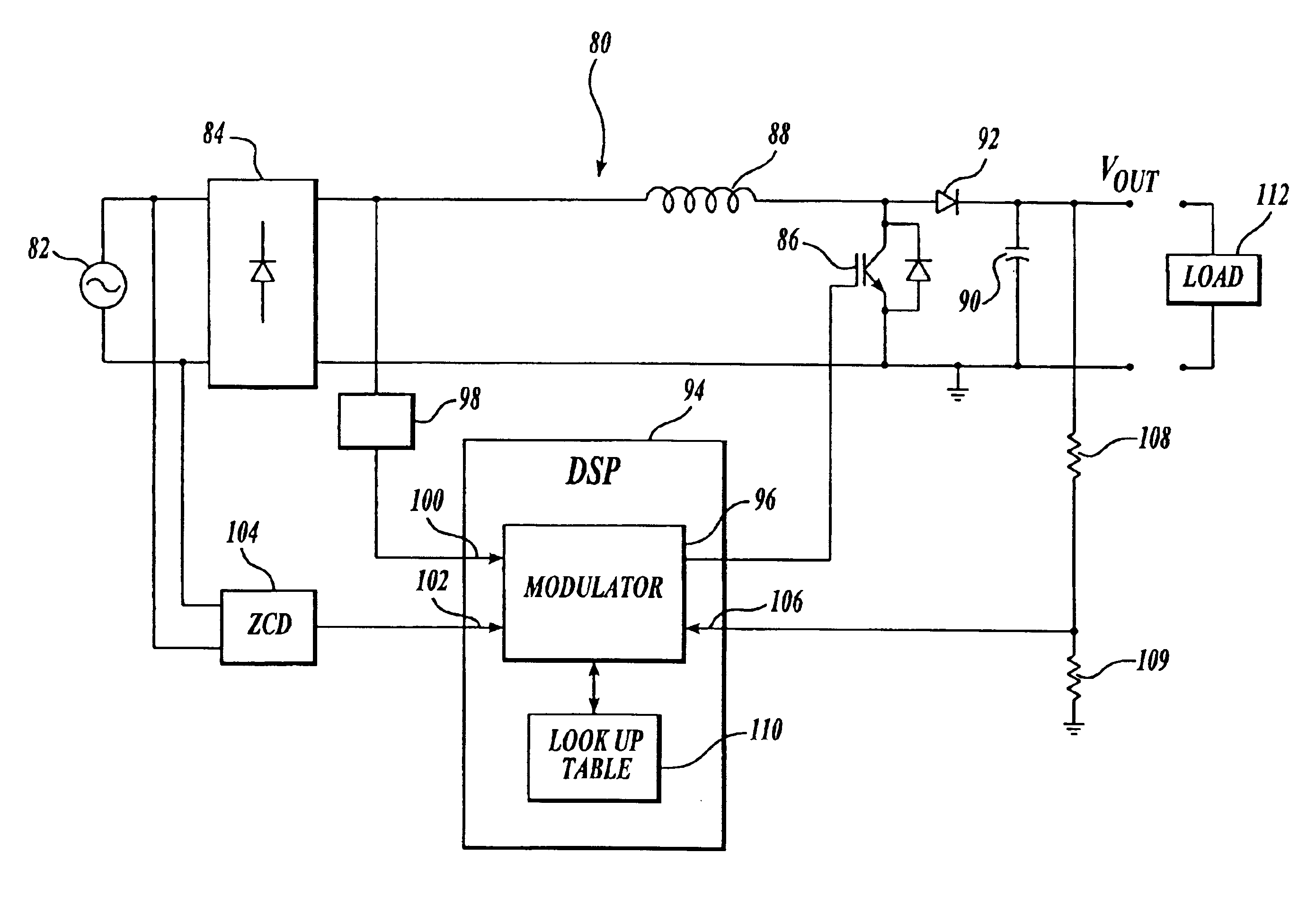
[0046]FIG. 4A is a diagram of one exemplary circuit 80 constructed in accordance with the principles of the present invention. The circuit 80 receives input voltage and current from an AC power source 82, such as a line current obtained from an electrical wall outlet. In this circuit, the input voltage from the power source 82 is rectified by a full-wave rectifier ...


PUM


Abstract

A combined power supply and driver control module includes rectifier circuitry, switching circuitry, and driver circuitry for providing output power to a load. Rectified output from an input power source is used to produce a DC power. The switching circuitry receives the DC power and modulates the input current drawn from the power source. An intelligent control module includes control circuitry, such as a digital processor, for controlling the switching circuitry. Power factor is improved by modulating the input current to be closer in phase with the voltage of the power source. Also disclosed is a power factor correction circuit in which a digital processor reads waveform values from a lookup table and modulates the input current waveform based on the values. A zero crossing detector connected to the input power source may direct the digital processor when to commence reading values from the lookup table.

Description

CROSS-REFERENCE TO RELATED APPLICATION[0001]This application claims the benefit of the filing date of U.S. Provisional Patent Application No. 60 / 351,961, filed Jan. 25, 2002.FIELD OF THE INVENTION[0002]The present invention is directed to a controller for a power supply that provides electrical power to a load, such as a motor, and more particularly, to a power supply controller with power factor correction features.BACKGROUND OF THE INVENTION[0003]A variety of applications use power supplies to provide electrical power to a load. A power supply may receive electrical power from a line source, such as a wall outlet, and convert the power for use in a particular application. A load may respond to the delivery of power in a linear manner, such as a purely resistive load, or the response may be nonlinear. An induction motor that is used to drive typical exercise equipment is one example of a nonlinear load.[0004]In one aspect, a power supply may convert an input line current from alter...

Claims


Application Information

Patent Timeline
Patent Type & Authority Patents(United States)
IPC IPC(8): H02M7/5387H02M1/00H02M1/42
CPCH02M1/4225H02M7/53873Y02B70/126H02M2001/0012Y02B70/10H02M1/0012H02M1/0085
Inventor LOPEZ-SANTILLANA, JUAN-LUISOLARIU, LAURENTIUPROTHERO, ROBERT MICHAELHUGHES, LEWIS V.LE-HUY, HOANG
Owner PRECOR
Why Eureka
Try Eureka