Device for visual identification of cables or conduits

a technology for visual identification and cables, applied in the direction of line-transmission details, coupling device connections, instruments, etc., can solve the problems of insufficient options, difficult to follow, and first method is not very practical, and achieves the effect of simple and inexpensive manner

Inactive Publication Date: 2005-06-14
BRUNET +1
View PDF17 Cites 50 Cited by
  • Summary
  • Abstract
  • Description
  • Claims
  • Application Information

AI Technical Summary

Benefits of technology

[0013]The present invention eliminates the drawbacks of all of the current methods or means mentioned above, by providing a device allowing the ends of leads, wires, cables, conduits or the like to be identified with certainty, whatever their number and their arrangement, without interrupting the link created by these leads, wires, cables or conduits, and therefore without stopping the operation of the connected systems, and without electromagnetic or other interference, and to do so in a particularly simple and inexpensive manner.

Problems solved by technology

In various technical fields using networks of relatively numerous wires, cables or conduits, the practical problem arises of being able, by knowing the position of one end of a wire, cable or conduit, to identify the position of the other end of the same wire, cable or conduit in a precise and certain manner.
More particularly in the case of cabinets referred to as “jumper” cabinets for computer links, many “jumper” leads are passed between the active computer hardware and the jumper panels, and it is very difficult to follow a lead over its entire length, from one of its ends, in order to be able to find its other end and thus make the link between a connector of given number of the distribution cable assembly and a port number of an active hardware item.
However, this first method is not very practical, and a source of errors, in the case of many entangled leads;another method consists in marking the cables or leads at both their ends, by labeling them.
Each cable or lead end is thus identified in theory, but there is an obvious difficulty in rapidly locating an end of a lead already in place (from a multiplicity of leads);it is also possible to distinguish the cables or leads by different external colors, but this method does not offer sufficient options, the maximum number of colors available being of the order of ten;another method may consist in disconnecting the cables or leads, in order to identify them according to the consequence of their disconnection, but this means a temporary stoppage of the operation of the system connected to the cable or lead that has been disconnected, which stoppage is in many cases unacceptable;one technical solution available consists of specific software and a specific database.
However, this solution is complex to manage, a source of errors during updating, and very expensive;it is also possible to use an automatic acquisition system, but the latter solution, involving the addition of an electrical conductor in each cable or lead, is a source of electromagnetic interference when injecting an electrical signal into the additional conductor.
Thus, such a solution is particularly expensive, given the large number of cables or leads that have to be equipped therewith.
In addition, the electrical conductors of this system may create electromagnetic interference.

Method used


Image

  • Device for visual identification of cables or conduits
  • Device for visual identification of cables or conduits
  • Device for visual identification of cables or conduits

Examples


Embodiment Construction

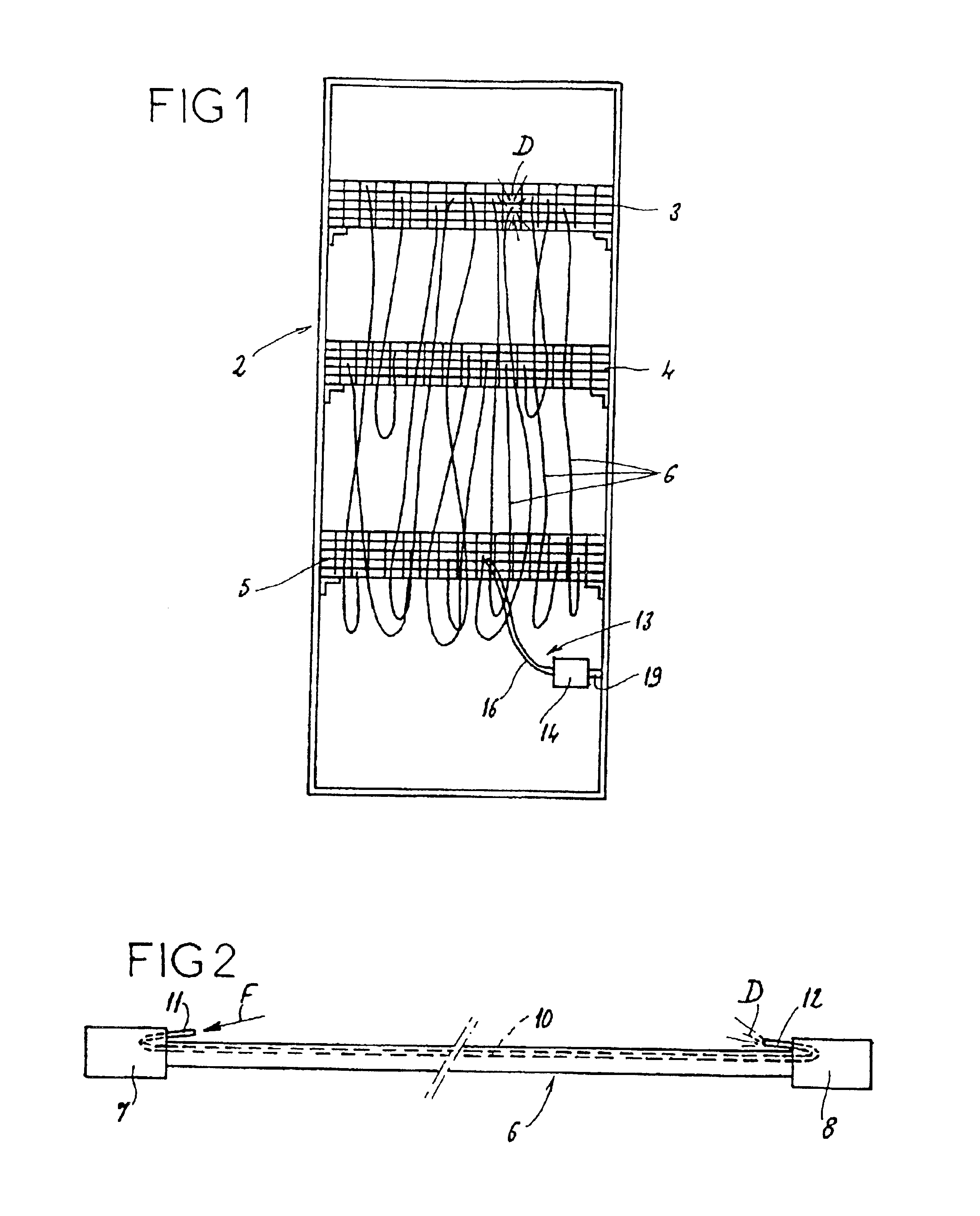
[0039]The invention is described below and illustrated by the drawing in the context of its particular application to locating the ends of computer jumper leads in a jumper cabinet.

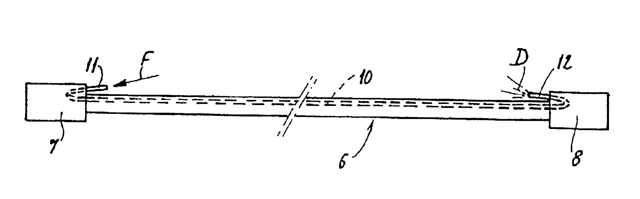
[0040]FIG. 1 shows, very schematically, such a computer jumper cabinet, denoted overall by the reference 2. This jumper cabinet 2 comprises items of computer hardware 3, 4, 5, which are active or used for distribution purposes, connected together via usually a large number of jumper leads 6. As shown in FIG. 2, each jumper lead 6 possesses, at both its ends, respective connectors 7 and 8, such as standardized connectors of the “RJ-45” type, allowing the items of computer hardware 3, 4, 5 to be connected.

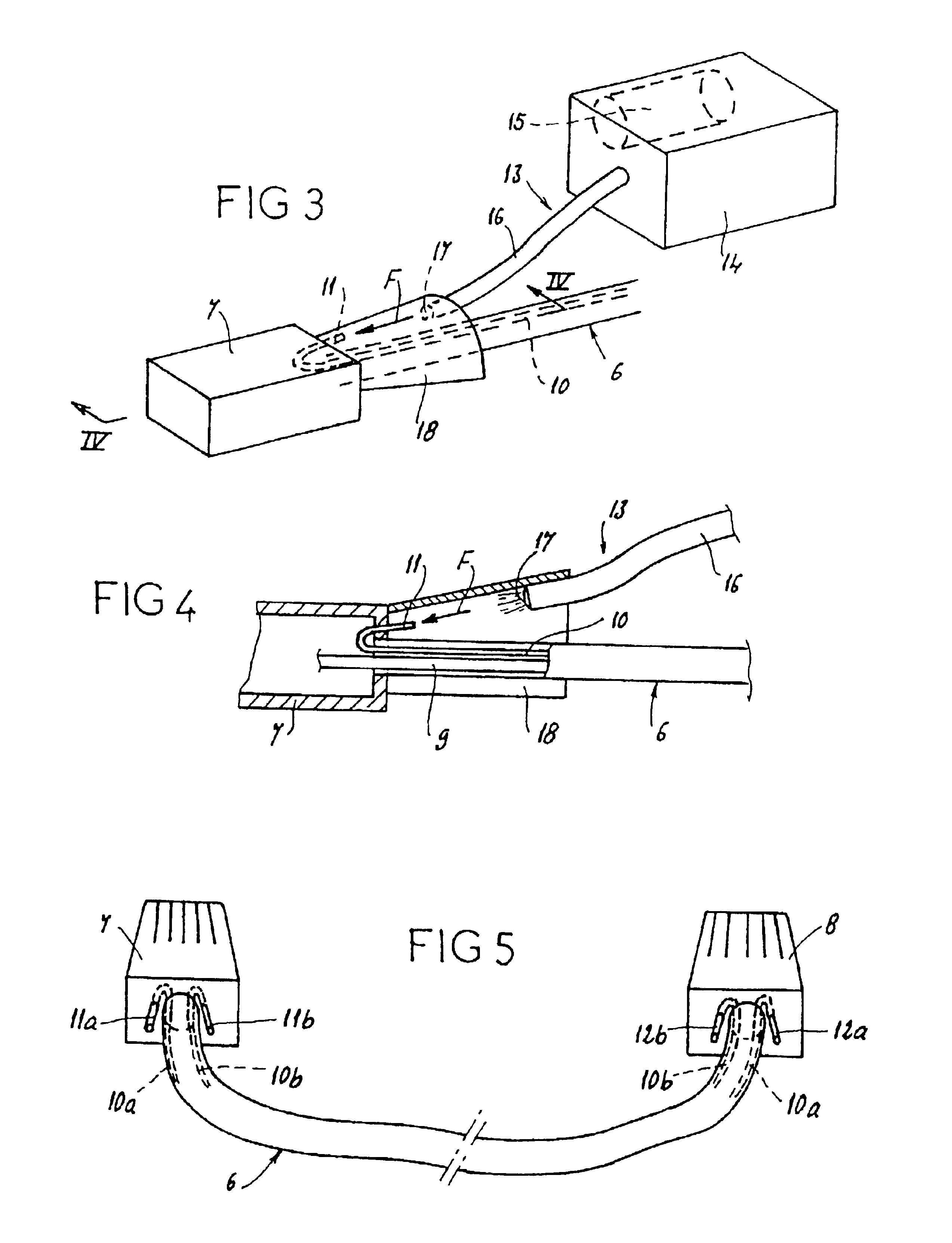
[0041]According to the invention, and as shown in FIGS. 2 to 4, each jumper lead 6 has, apart from conductors 9 extending from one connector 7 to the other 8, at least one optical fiber 10 which, again, extends over the entire length of this lead 6, from one end of the latter to the other.

[0042]The optical...


PUM


Abstract

The invention provides a device for accurately locating ends of cords, wires cables or conduits, in particular in the fields of electricity, electronics, telephone and computer. The device includes an optical fiber disposed on a cord and extending from a first end to a second end of the cord. The optical fiber includes a first fiber end disposed at the first end of the cord and a second fiber end disposed at the second end of the cord. The device further includes a means for injecting light disposed proximate the first fiber end, the first fiber end being accessible so as to be illuminated by the means for injecting light and the second fiber end being accessible so as to recover the light injected at the first fiber end. Said device is useful for locating computer switching cords.

Description

FIELD OF INVENTION[0001]The present invention relates to a device for visual identification of cable assemblies or conduits, more particularly, a device which makes it easier to locate the ends of leads, wires or cables used in the following fields: electrical, electronic, telephone, computing, automatic control etc., or else to locate the ends of rigid or flexible conduits through which fluids flow and which belong to hydraulic or pneumatic or other installations.BACKGROUND OF INVENTION[0002]In various technical fields using networks of relatively numerous wires, cables or conduits, the practical problem arises of being able, by knowing the position of one end of a wire, cable or conduit, to identify the position of the other end of the same wire, cable or conduit in a precise and certain manner. Such is the case, in particular, with leads called computer “jumper” leads, housed in a cabinet or a case, telephone “patching” systems, or wires and cables of electrical cable assemblies,...

Claims


Application Information

Patent Timeline
Patent Type & Authority Patents(United States)
IPC IPC(8): G02B6/44G02B6/00
CPCH01R13/7172G02B6/4415G02B6/562
Inventor BRUNETTANDE, ERIC
Owner BRUNET
Why Eureka
Try Eureka