Security relay

a relay and security technology, applied in the field of relays, can solve the problems of tensile warping and inability to retain optimal dimensional stability

Inactive Publication Date: 2005-06-14
TYCO ELECTRONICS AUSTRIA
View PDF13 Cites 22 Cited by
  • Summary
  • Abstract
  • Description
  • Claims
  • Application Information

AI Technical Summary

Benefits of technology

[0006]The object of the present invention is to construct a relay of the type mentioned at the outset such that the characteristic curve of the spring can be better adapted to that of the magnet system.

Problems solved by technology

Laterally open actuating portions alter the stability of the slide, however, with the result that such slides already have a tendency to warp even during manufacture and do not retain optimum dimensional stability in operation either.
A further problem with relay constructions of this kind consists in the fact that the force for opening the opening springs has to be overcome at the beginning of the movement of attraction of the armature, while the force for closing the closing contacts occurs towards the end of the armature movement of attraction.
Since the force of an electromagnet system is small at the beginning of the armature movement of attraction, however, and only rises steeply towards the end of the movement of attraction, when the operational air gap is almost closed, application of the opening force is a problem which is typically solved by making the magnet system large in size, with this over-sizing not being necessary to close the closing contacts.

Method used


Image

  • Security relay
  • Security relay
  • Security relay

Examples


Embodiment Construction

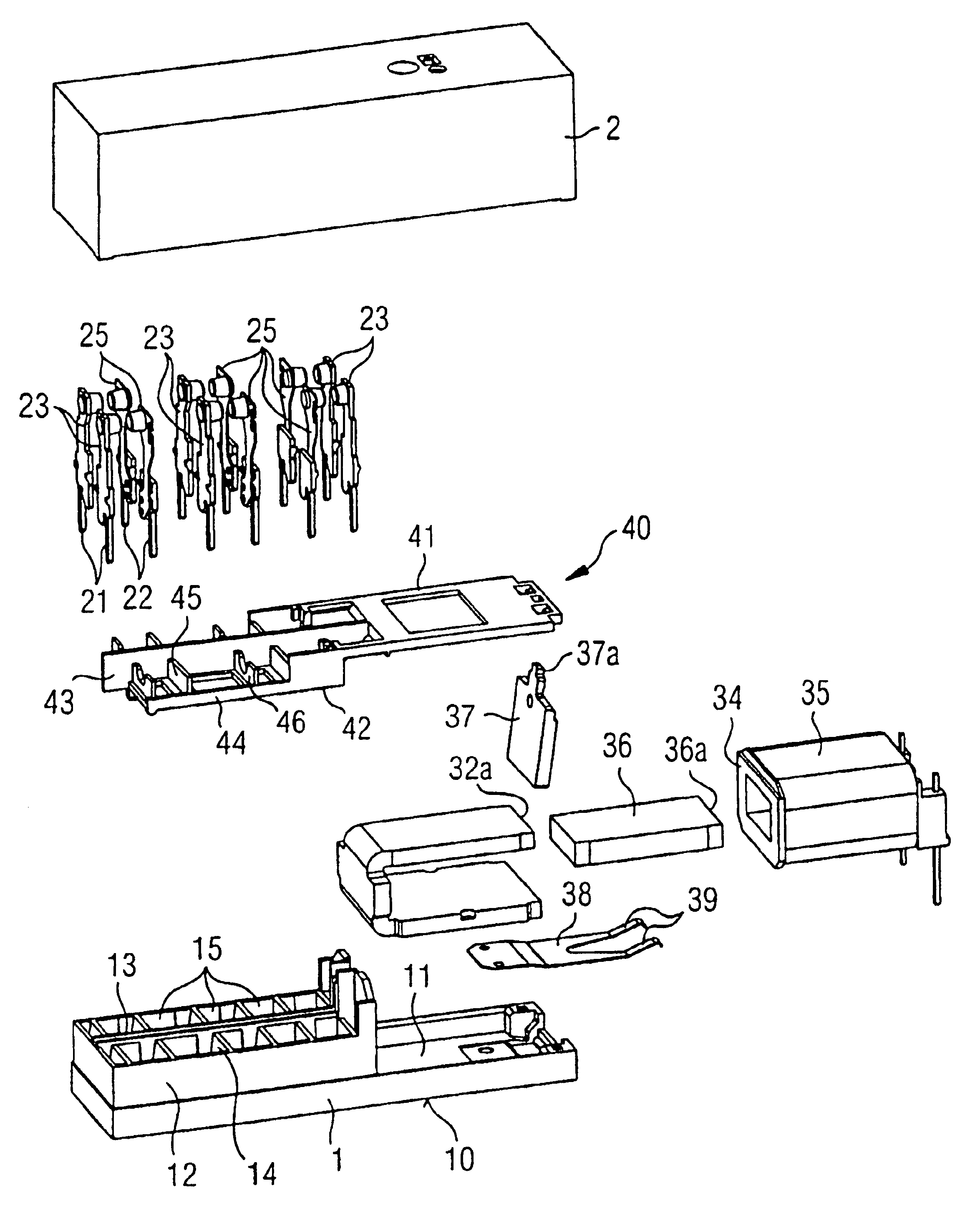
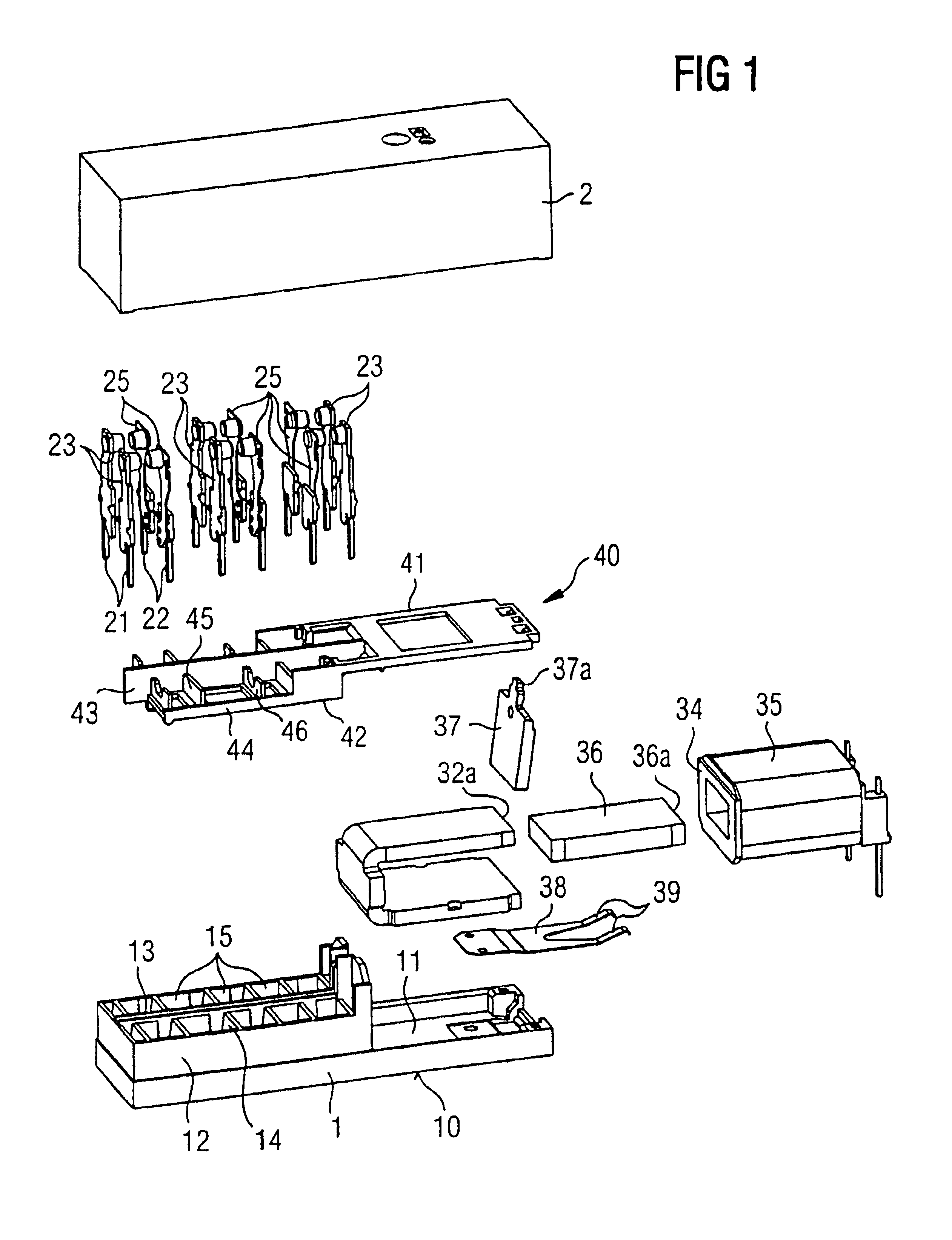
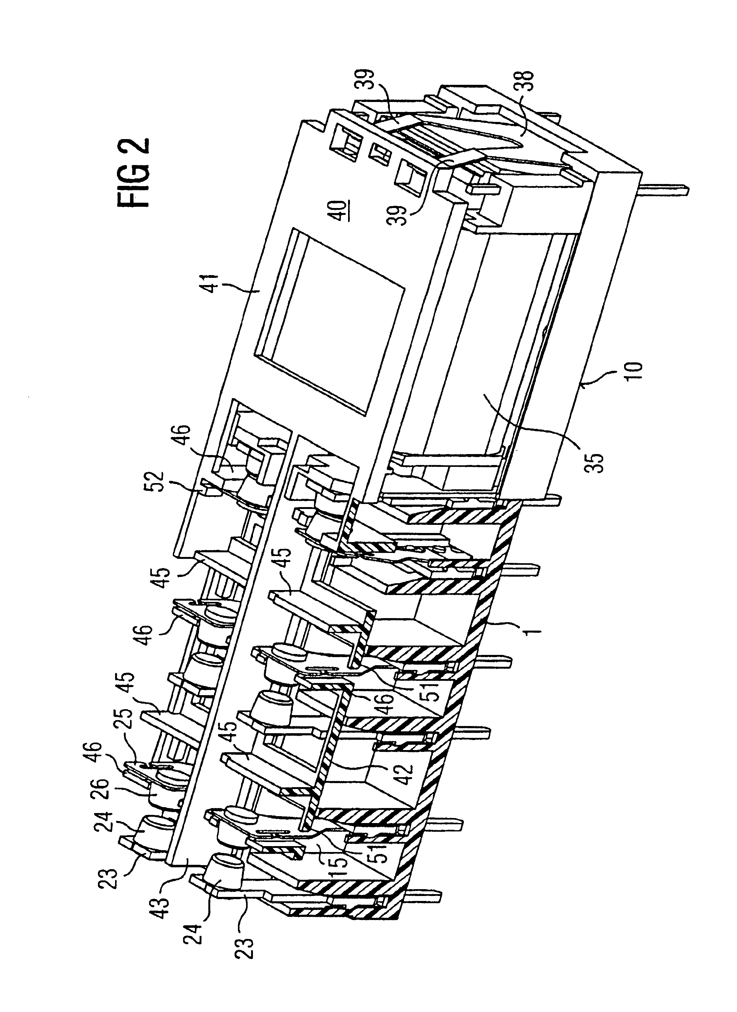
[0017]The relay illustrated in FIGS. 1 to 6 has a base 1 made of insulating material, which is substantially flat in form and defines a base side 10, and with a cover 2 forms a closed housing. The base 1 has a flat, trough-shaped recess 11 for receiving a magnet system, while the remaining part, having raised side walls 12, a longitudinal intermediate wall 13 and transverse walls 14, forms two rows of contact beam chambers 15. These contact beam chambers 15 narrow downwardly in the manner of slots to form plug-type channels 16 (see FIG. 4), in order to receive fixed contact beams 21 or spring contact beams 22 which may be plugged in, in each case from above, perpendicularly to the base plane 10. The fixed contact beams 21 each form at their free ends passive (or fixed) spring contacts 23 with fixed contact portions 24 secured thereto, while active (or movable) spring contacts 25 with movable contact portions 26 secured to their free ends are in each case secured to the spring contac...


PUM


Abstract

A relay having a base on which is arranged an electromagnetic system that actuates at least one pair of closing contact springs and at least one pair of opening contact springs where actuation is effected by a slide having actuation lugs located at different heights relative to the fixing of the active spring contacts for actuating the active opening spring contacts at a height different from that of the active closing spring contacts so that the characteristic curve of the magnetic system can be better adjusted to that of the spring contacts.

Description

BACKGROUND OF THE INVENTION[0001]The present application is related to PCT application EP 99 / 07278 filed on Oct. 1, 1999 and claims the priority data thereof.[0002]1. Field of the Invention[0003]The invention relates to a relay, having: a base which defines a base plane; a magnet system arranged on the base and having a coil, a core and an armature; at least one pair of closing spring contacts and at least one pair of opening spring contacts, each pair of spring contacts including an active and a passive spring contact, and each spring contact being secured in the base, standing perpendicular to the base plane, and bearing at its end remote from the base a contact portion; and an actuating slide which is movable parallel to the base plane and which acts on each movable spring contact, in each case in the vicinity of the contact portion.[0004]2. Summary of the Prior Art[0005]A relay of this type with forcibly guided contacts is known from DE 195 40 739 A1. There, the individual conta...

Claims


Application Information

Patent Timeline
Patent Type & Authority Patents(United States)
IPC IPC(8): H01H50/00H01H50/64
CPCH01H50/642
Inventor MADER, LEOPOLDMIKL, RUDOLF
Owner TYCO ELECTRONICS AUSTRIA
Why Eureka
Try Eureka