
Constant current source with threshold voltage and channel length modulation compensation

a constant current source and channel length technology, applied in the direction of logic circuit coupling/interface arrangement, pulse technique, instruments, etc., can solve the problem that the current source cell 30/b> in fig. 3 cannot meet the requirements of a high resolution dac, and the resolution of the dac is not high enough to achieve the effect of robust performance and superior psrr

Inactive Publication Date: 2005-06-14
SPIROX INC
View PDF13 Cites 3 Cited by
  • Summary
  • Abstract
  • Description
  • Claims
  • Application Information

AI Technical Summary

Benefits of technology

The present invention provides a constant current source with threshold voltage and channel length modulation compensation. This compensation circuit is added in the circuit of a current source cell, which enables a robustness performance in a whole current source that possess a superior PSRR. Additionally, the invention provides an optimal circuit design for the current source, which can be widely applied in the DAC circuit design by adjusting corresponding parameters to minimize the variance of an output current. The constant current source includes five MOS transistors and a loading impedance, which work together to achieve the desired current output.

Problems solved by technology

Furthermore, they need to be accompanied with high-efficiency operational amplifiers to have a good performance, so most current circuit designs don't adopt passive components and tend to adopt active components.
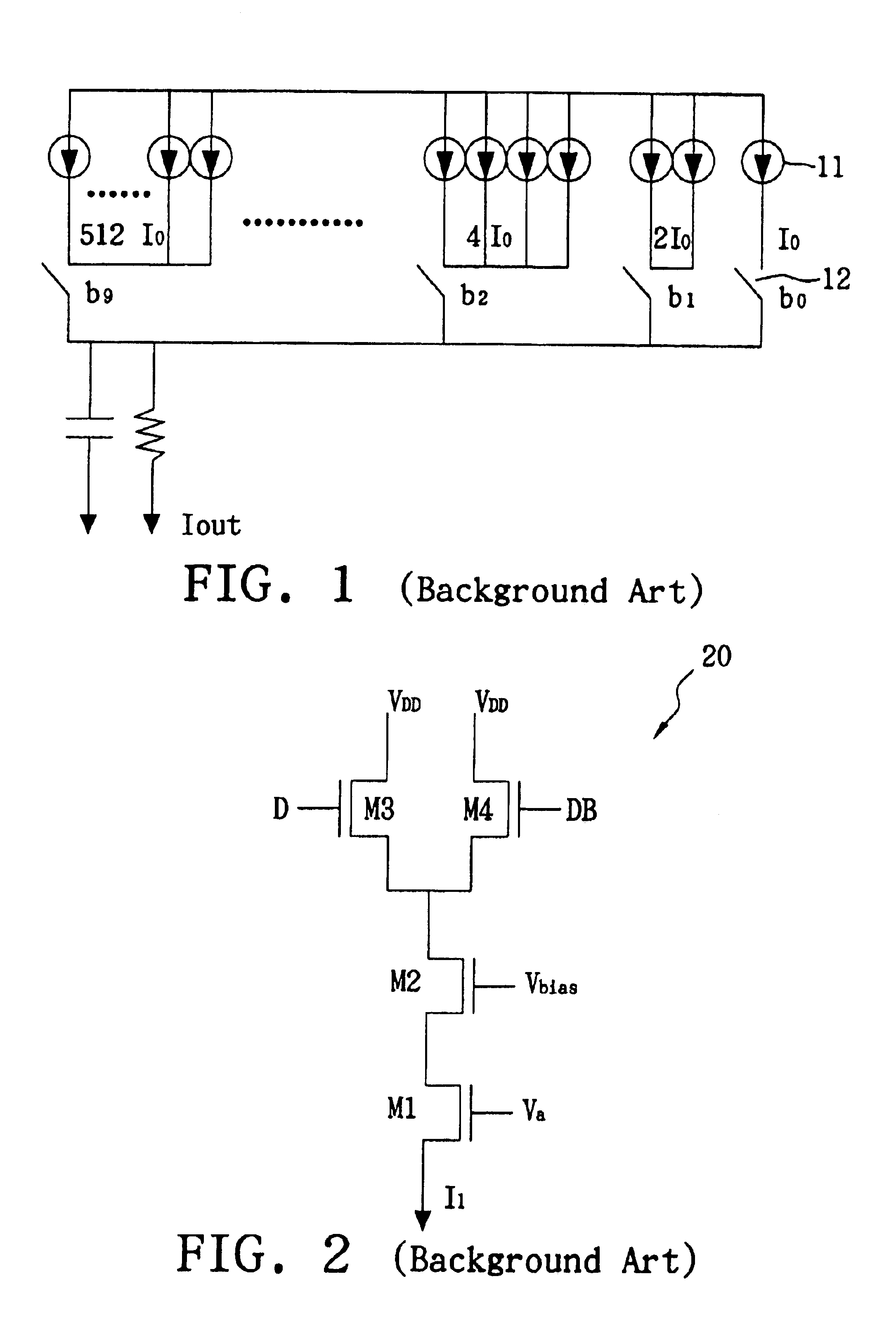
However, because the aforementioned circuit makes use of more than one thousand current source cells 11, the homogeneities of the current source cells 11 output current are very important; otherwise, it is impossible to obtain a DAC with a high resolution or high yield ratio.
In addition, not only the threshold voltage Vth may shift with the manufacture process conditions, but also the great current source cells of a DAC may have a poor PSRR (Power Supply Rejection Ratio; PSRR), which results in a distorted conversion.
However, the current source cell 30 in FIG. 3 still cannot meet the requirements of a high resolution DAC.

Method used


Image

  • Constant current source with threshold voltage and channel length modulation compensation
  • Constant current source with threshold voltage and channel length modulation compensation
  • Constant current source with threshold voltage and channel length modulation compensation

Examples


Embodiment Construction

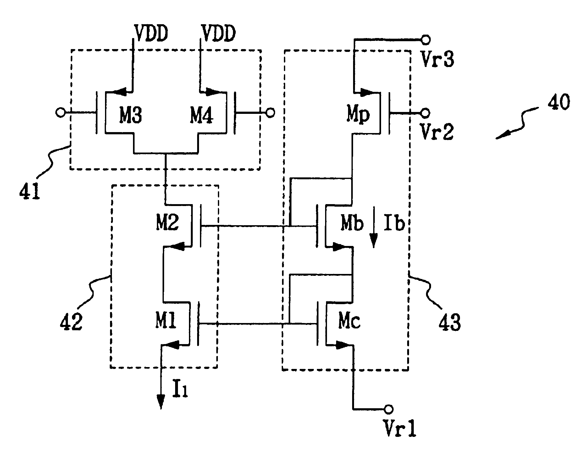
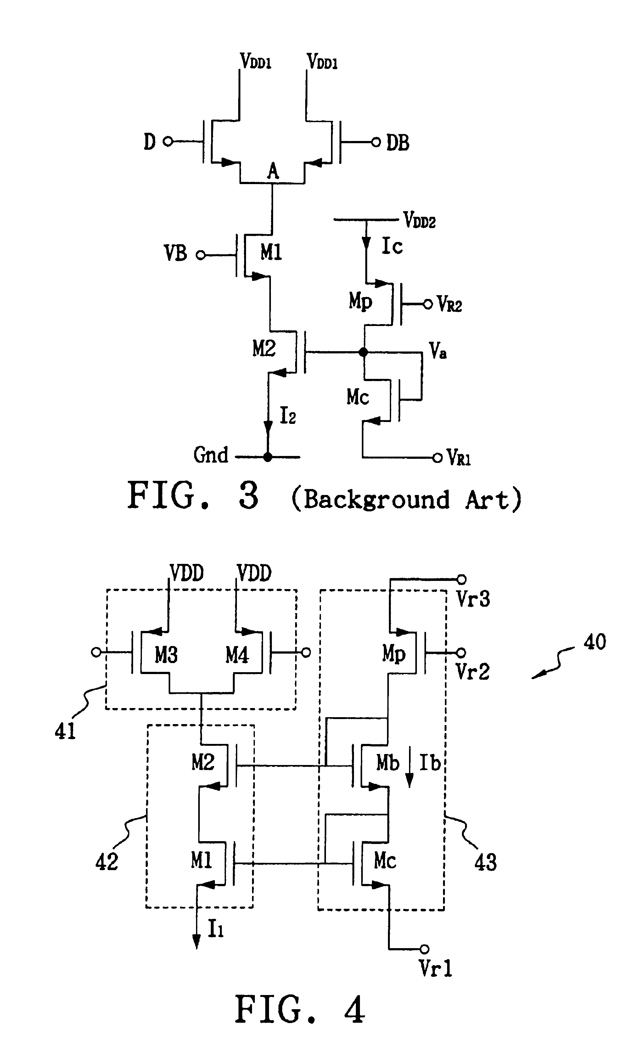
[0022]FIG. 4 is a circuit diagram of a current source cell in accordance with the present invention. The current source cell 40 of the present invention includes a first MOS transistor M1, a second MOS transistor M2, a third MOS transistor Mb, a fourth MOS transistor Mc and a fifth MOS transistor Mp. In addition, a MOS transistor M3 and a MOS transistor M4 can be added to the circuit as a switch circuit 41 that can control the direction of an input current. Furthermore, the voltage VDD of the first power supply is together coupled to the source electrodes of the P-type MOS transistor M3 and MOS transistor M4. The first MOS transistor M1 and the second MOS transistor M2 form a cascade transistor 42. The third MOS transistor Mb, the fourth MOS transistor Mc and the fifth MOS transistor Mp form a compensation circuit 43 that can reduce the influences of threshold voltage of the cascade transistor 42 on the output current I1.

[0023]The drain electrode of the second MOS transistor M2 is c...


PUM


Abstract

A constant current source with threshold voltage and channel length modulation includes first, second, third, fourth and fifth MOS transistors. Each of the MOS transistors has gate, first and second terminals. The first terminal of the second MOS transistor is coupled to loading impedance, and its second terminal is coupled with the first terminal of the first MOS transistor. The gate terminal and first terminal of the third MOS transistor are together coupled to the gate terminal of the second MOS transistor, and its second terminal is coupled to the first terminal of the fourth MOS transistor. The gate terminal and first terminal of the fourth MOS transistor are coupled to the gate terminal of the first MOS transistor, and its second terminal is coupled to a first reference voltage. The gate terminal and second terminal of the fifth MOS transistor are respectively coupled to a second reference voltage and a third reference voltage, and its first terminal is coupled to the gate terminal and first terminal of the third MOS transistor.

Description

BACKGROUND OF THE INVENTION[0001]1. Field of the Invention[0002]The present invention relates to a constant current source with threshold voltage and channel length modulation compensation, and more particularly to a current source that is applicable to digital-analog converter (DAC).[0003]2. Description of the Related Art[0004]DAC is the most commonly used circuit in integrated circuit (IC) design fields, and can usually be divided into active component type and passive component type. Passive DAC applies resistors or capacitors to complete such a circuit design. Because the passive components have a larger chip thereon, the matching between these passive components has to be taken into consideration. Furthermore, they need to be accompanied with high-efficiency operational amplifiers to have a good performance, so most current circuit designs don't adopt passive components and tend to adopt active components.[0005]The active components generally can be divided into weighted curren...

Claims


Application Information

Patent Timeline
Patent Type & Authority Patents(United States)
IPC IPC(8): G05F3/26H03K17/041
CPCG05F3/262H03K17/04106
Inventor YANG, CHING HSIANGLIN, CHUN WEI
Owner SPIROX INC
Learn More