
Audio amplification device with antipop circuitry

a technology of anti-pop circuitry and audio amplification device, which is applied in the direction of dc-amplifiers with dc-coupled stages, low frequency amplifiers, amplifiers, etc., can solve the problems of voltage spike, degraded psrr (power supply rejection ratio) during the normal operation phase, and sound of voltage spike, so as to avoid the risk of a pop still being generated, good psrr, and good operation of differential pairs

Inactive Publication Date: 2007-06-05
ST ERICSSON SA
View PDF11 Cites 14 Cited by
  • Summary
  • Abstract
  • Description
  • Claims
  • Application Information

AI Technical Summary

Benefits of technology

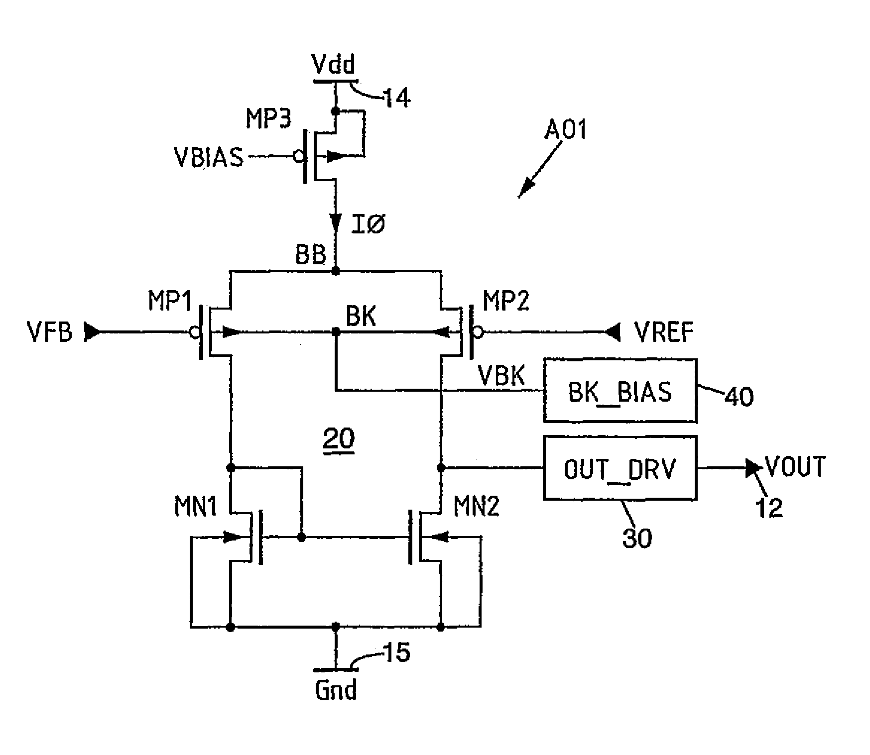
[0011]Thus, the following advantages are combined: a good operation of the differential pair of MOS transistors for low values of the reference voltage (in other words, at the beginning of the ramp) which avoids the generation of a pop when the power is turned on, and a good PSRR when operating in the normal regime.
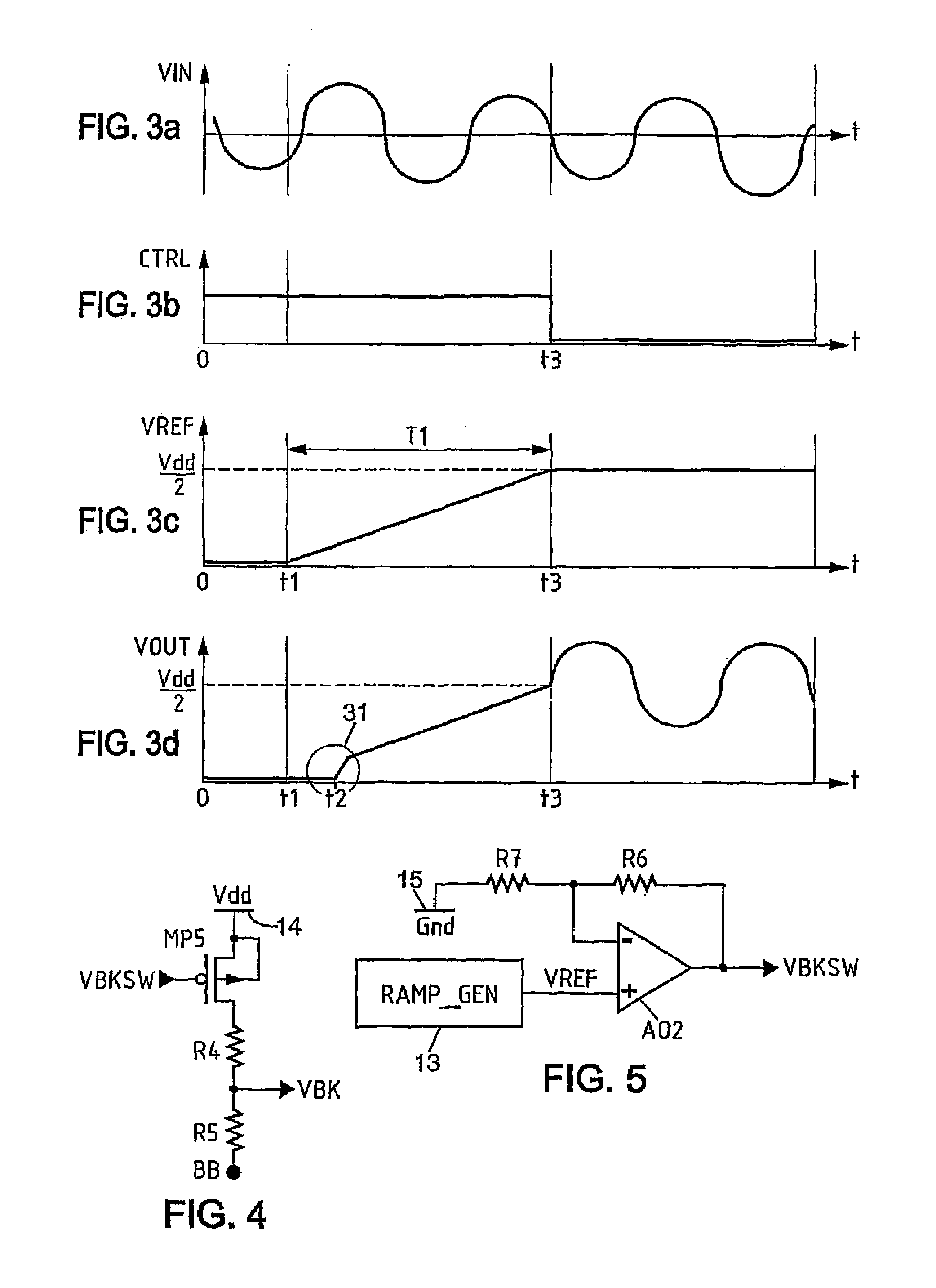
[0012]In one advantageous embodiment, the biasing circuitry provides a smooth transition of the bulk voltage of the first and second MOS transistors from the first voltage to the second voltage. This avoids the risk of a pop still being generated, which could be the case for a more abrupt transition.
[0014]Advantageously, the ramp generator can generate the reference voltage. Thus, the implementation of the invention does not require an additional ramp generator, since the same ramp generator is used for generating the reference voltage and for providing the smooth transition of the bulk bias voltage of the differential pair of MOS transistors.
[0016]In one embodiment, the gate of the first MOS transistor is connected to the input of the device via a controlled switch, for example an MOS transistor, which is open when the amplifier is powered up and is closed in the normal operation phase. In this way, the application of the input audio signal onto the gate of the first MOS transistor is prevented during the power-up phase. The generation of pops, originating from the audio signal itself, is thus avoided during this phase.

Problems solved by technology

In this case, however, the PSRR (Power Supply Rejection Ratio) is degraded during the normal operation phase.
However, on powering up the amplifier, the latter will only operate when the drain-source voltage of the MOS transistors of the differential pair has reached about 0.1 V. Since the amplifier operates as a follower of the reference voltage during the power-up phase, the abrupt starting of the operation of the differential pair generates a voltage spike in the audio output signal.
This voltage spike is heard as a pop and is therefore problematic.

Method used


Image

  • Audio amplification device with antipop circuitry
  • Audio amplification device with antipop circuitry
  • Audio amplification device with antipop circuitry

Examples


Embodiment Construction

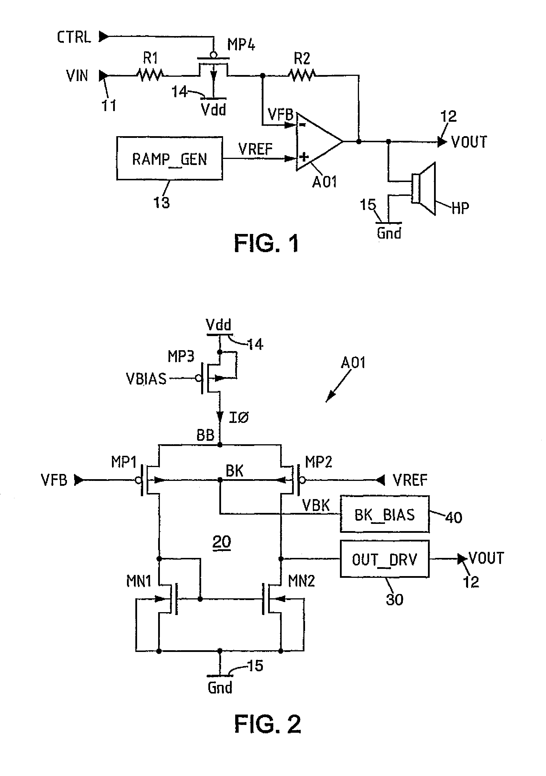
[0033]In FIG. 1, a schematic circuit diagram is shown of an example of an audio amplification circuit to which the present invention may be applied.

[0034]The audio amplification circuit includes an input 11 for receiving an audio input signal VIN to be amplified. It also includes an output 12 delivering an audio output signal VOUT corresponding to the signal VIN after amplification. The signal VOUT is a signal suitable for driving a sound reproduction device such as a loudspeaker or headphones. Typically, the output 12 drives a loudspeaker of the appliance in which the audio amplification circuit is used, or a headphone socket of this appliance to which a pair of headphones or earphones or, alternatively, an external loudspeaker can be connected. In the case depicted here, a loudspeaker HP is shown connected in parallel between the output 12 and a ground terminal 15 having a ground potential Gnd.

[0035]In the present description, all the voltages mentioned are referenced to the groun...


PUM


Abstract

An audio amplification device includes an input for receiving an input audio signal and an output for delivering an output audio signal and an amplifier (OA1) comprising a differential pair of MOS transistors. The gate of the first transistor is coupled to the input of the device. The gate of the second MOS transistor receives a reference voltage which takes the form of a rising ramp when the power is turned on. The drain of one of the transistors is coupled to the output. The amplifier also includes a biasing circuitry for biasing the bulk of the transistors to a first voltage level approximately equal to a supply voltage at the beginning of the reference voltage ramp, and to a second voltage level (VBB) approximately equal to the voltage of their source at the end of the ramp. The generation of a pop is thus avoided when the power is turned on, while still benefiting from an optimum PSRR in the normal operation phase.

Description

BACKGROUND OF THE INVENTION[0001]1. Field of the Invention[0002]The present invention relates to the amplification of audio signals. It finds applications in all audio appliances, in particular in mobile phones. In such an application, an audio amplification device is designed to drive the loudspeaker or the headphone socket of a mobile phone.[0003]2. Description of the Related Art[0004]Typically, an audio amplifier is biased in the mid-range of the voltages available, in other words, for example, at a reference voltage equal to Vdd / 2 for an audio amplifier supplied between a positive supply voltage Vdd and ground. The maximum dynamic range is thus obtained for the amplification of an input audio signal. For example, the amplifier possesses an input stage having a differential structure which amplifies the difference between the input audio signal and the reference voltage.[0005]When turning on the power to the audio amplifier, in order to avoid the production of an audible parasiti...

Claims


Application Information

Patent Timeline
Patent Type & Authority Patents(United States)
IPC IPC(8): H03F3/45H03F1/30H03F3/185H03G3/34
CPCH03F1/305H03F3/185H03F3/45475H03F2200/03H03F2200/186H03F2200/78
Inventor MARTY, NICOLAS
Owner ST ERICSSON SA
Learn More