
Mixed-mode PLL

a mixed-mode, phase locked technology, applied in the direction of electrical equipment, automatic control of pulses, etc., can solve the problems of in-band phase noise, in-band phase noise, inability to filter loops, etc., to reduce noise and spur, improve psrr, and eliminate noise and spur

Active Publication Date: 2010-09-07
MEDIATEK INC
View PDF2 Cites 27 Cited by
  • Summary
  • Abstract
  • Description
  • Claims
  • Application Information

AI Technical Summary

Benefits of technology

The solution results in a PLL that is insensitive to non-linearity and quantization errors, achieving lower phase noise, twice the loop bandwidth, and being fractional spur-free, with improved power supply rejection ratio (PSRR) and reduced transient noise.

Problems solved by technology

However, this PLL is still limited to integer-N operations, because quantization errors of a digital PFD increases noise and spur in fractional-N operations.
However, the in-band noises induced by the TDC still can not be filtered by the loop.
Moreover, less DCO noise is filtered by the loop due to the narrower loop bandwidth, and in-band phase noise is thus consequently increased.
A digital loop filter or a digital algorithm cannot eliminate the induced spurs since the quantization itself can not be cancelled by only using a digital algorithm.
Quantization errors of a DCO cannot be filtered by the loop because the noise transfer function of the DCO is a high pass filter, even when a high speed sigma delta modulator is used to obtain fine frequency resolution.
The short-term quantization errors of the DCO is sampled back to the loop and amplified due to gain variation of the TDC, resulting in spurs.
The digitally-implemented ring type TDC is more sensitive to the power supply due to the ring based design, because the high frequency noises induced by power noise of TDC are aliased to a low frequency domain, which cannot be filtered by the loop.

Method used


Image

  • Mixed-mode PLL
  • Mixed-mode PLL
  • Mixed-mode PLL

Examples


Embodiment Construction

[0021]The following description is of the best-contemplated mode of carrying out the invention. This description is made for the purpose of illustrating the general principles of the invention and should not be taken in a limiting sense. The scope of the invention is best determined by reference to the appended claims.

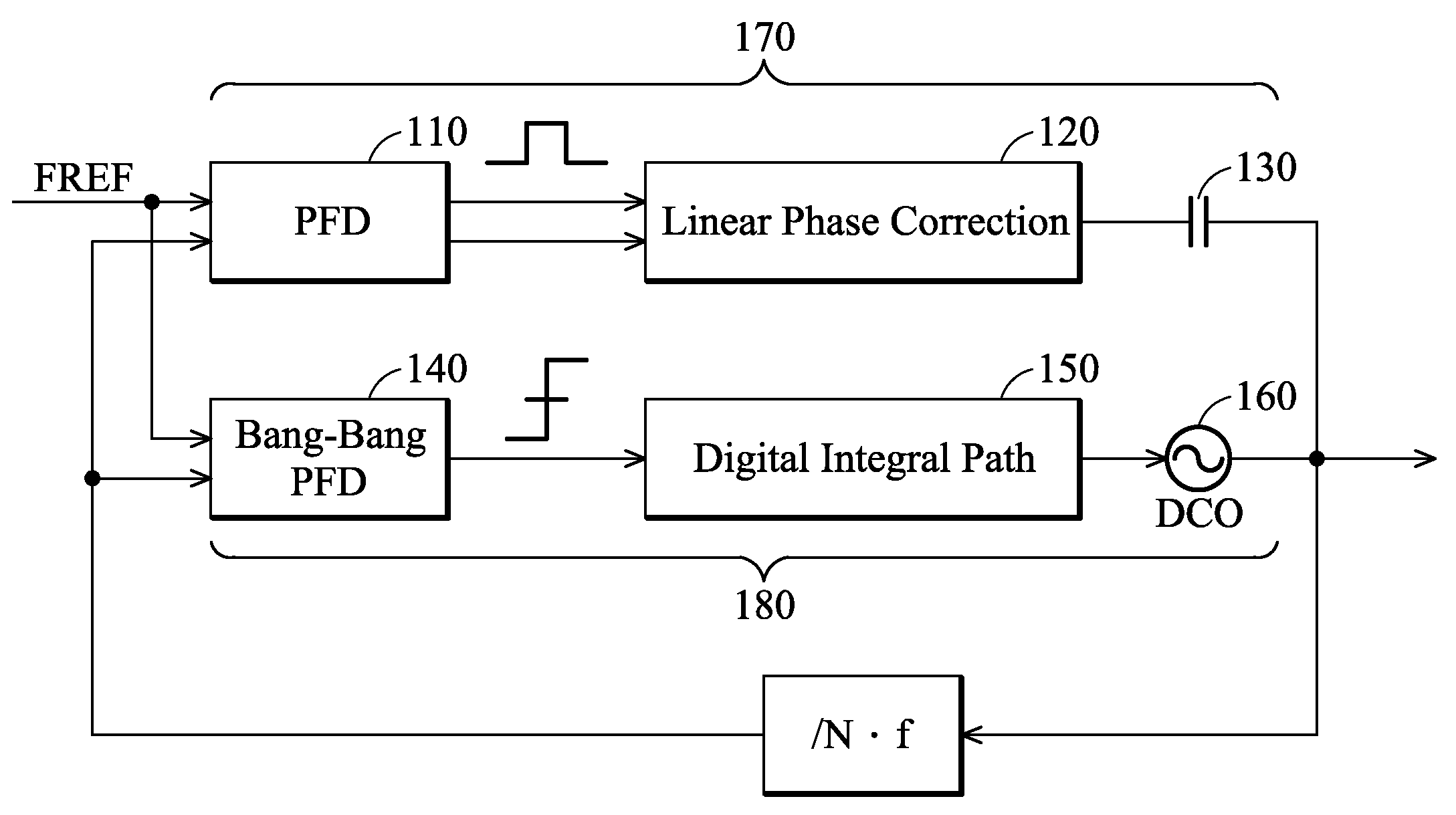
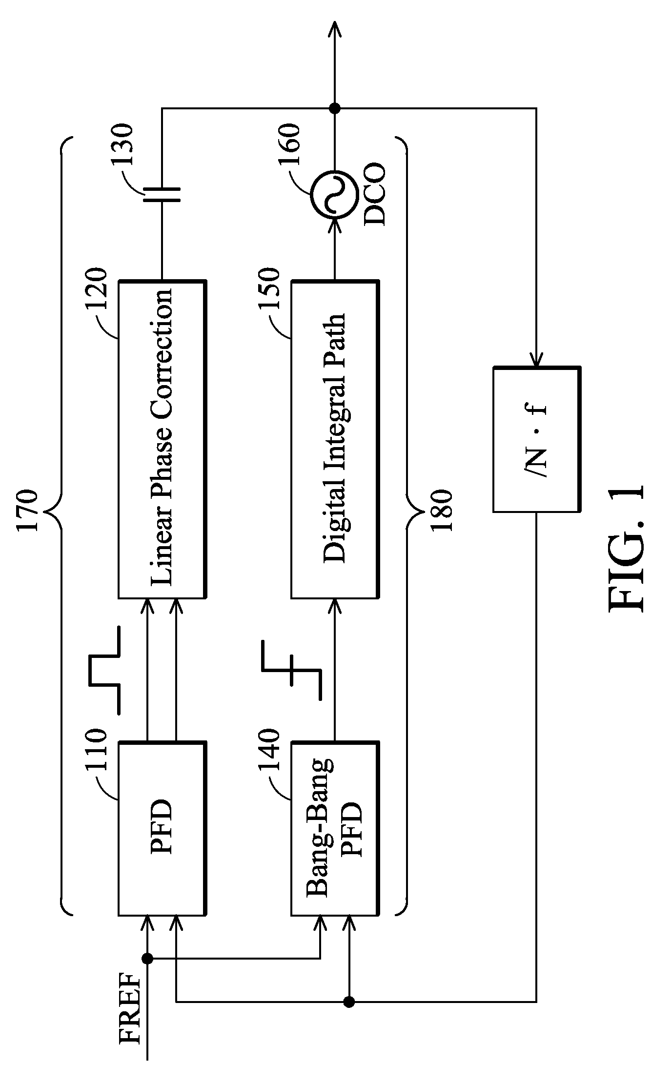
[0022]FIG. 1 is a block diagram of a mixed-mode PLL according to an embodiment of the invention. The mixed-mode PLL comprises an analog phase correction path 170 and a digital frequency correction path 180. The analog phase correction path 170 comprises a conventional phase frequency detector (PFD) 110 and a linear phase correction unit (LPCU) 120, which is coupled to a digital controlled oscillator (DCO) output by an AC coupling capacitor 130. The LPCU 120 corrects phase in a time domain generated by a conventional PFD 110 and thus avoids all the noise and spur induced by a time to digital converter (TDC) and a DCO 160. Specifically, the DCO 160 can be a ring oscillat...


PUM


Abstract

A mixed-mode PLL is disclosed. The mixed-mode PLL comprises an analog phase correction path and a digital frequency correction path. The analog phase correction path comprises a linear phase correction unit (LPCU). The digital frequency correction path comprises a digital integral path circuit.

Description

CROSS REFERENCE TO RELATED APPLICATIONS[0001]This application claims the benefit of U.S. Provisional Application No. 61 / 019,314, filed on Jan. 7, 2008, the contents of which are incorporated herein by reference.BACKGROUND OF THE INVENTION[0002]1. Field of the Invention[0003]The invention relates to a phase locked loop (PLL) and, in particular, to a mixed-mode PLL insensitive to quantization error.[0004]2. Description of the Related Art[0005]A digitally controlled oscillator-based (DCO-based) phase locked loop (PLL) uses a scalable digital loop filter which not only eliminates noise induced by gate oxide leakage but also digitally calibrates output frequency through a digital loop filter. However, this PLL is still limited to integer-N operations, because quantization errors of a digital PFD increases noise and spur in fractional-N operations.[0006]Quantization errors of a time to digital converter (TDC) can not be shaped to a higher frequency domain such that the loop bandwidth is r...

Claims


Application Information

Patent Timeline
Patent Type & Authority Patents(United States)
IPC IPC(8): H03L7/06
CPCH03L7/087H03L7/0991H03L7/113H03L7/18
Inventor WANG, PING-YINGZHAN, JING-HON CONAN
Owner MEDIATEK INC
Learn More