Mounting system for an optical assembly of a photoelastic modulator

a technology of photoelastic modulator and optical assembly, which is applied in the direction of instruments, non-linear optics, optics, etc., can solve the problems of requiring more drive energy, affecting the overall performance quality factor, and unsatisfactory changes in the birefringence characteristics of the optical elemen

Inactive Publication Date: 2005-06-14
HINDS INSTR
View PDF3 Cites 9 Cited by
  • Summary
  • Abstract
  • Description
  • Claims
  • Application Information

AI Technical Summary

Benefits of technology

[0007]The optical assembly is contained within a housing or enclosure that normally includes an aperture through which the light under study is directed through the optical element. The enclosure supports the optical assembly in a manner that permits the optical element to be driven (vibrated) within it to achieve the above noted photoelastic effect.
[0010]The prior technique for mounting the optical assembly to the enclosure is generally effective but has at least one drawback. Specifically, the use of the somewhat rigid, cone-shaped supports has deleterious effects on the overall performance quality factor, or “Q” value, of the photoelastic modulator. In this regard, “Q” is defined as the ratio of the energy stored in a system to the energy lost per cycle. The higher the “Q,” the more efficient the system. The rigid supports tend to dampen the vibration of the optical element, thus requiring more drive energy to maintain the desired vibrational frequency of the element. Increasing drive energy increases the heat generated within the photoelastic modulator, which causes a reduction in the Q value.
[0011]The present invention provides an improved system for mounting an optical assembly of a PEM to permit free vibration of the optical assembly without introducing any stress or strain on the optical element. Moreover, the mounting system facilitates accurate and easy assembly of the optical element into its enclosure.
[0013]As another aspect of this invention the mounted optical assembly is reliably attached to the enclosure, and able to withstand severe jarring of the PEM without failure of the mounting.
[0014]As another approach to mounting the optical assembly to permit its free vibration, a PEM is configured to reduce what is characterized as “residual” birefringence that may be attributable to supporting the optical element of the PEM in the enclosure. In this regard, the optical element is bonded at each end to a transducer. Each transducer is mounted to the PEM enclosure in accordance with the present invention. The mounting system also includes a specially shaped mount that has edges that abut the optical element, but are not bonded to that element. As a result, the optical element is essentially suspended, thus free from any residual birefringence that may be attributable to directly mounting the oscillating optical element to the enclosure. The specially configured version of the mount, however, secures that optical element against unwanted movement out of the direction that the element oscillates.

Problems solved by technology

Such stress or strain would result in undesirable changes in the birefringence characteristics of the optical element.
The prior technique for mounting the optical assembly to the enclosure is generally effective but has at least one drawback.
Specifically, the use of the somewhat rigid, cone-shaped supports has deleterious effects on the overall performance quality factor, or “Q” value, of the photoelastic modulator.
The rigid supports tend to dampen the vibration of the optical element, thus requiring more drive energy to maintain the desired vibrational frequency of the element.

Method used


Image

  • Mounting system for an optical assembly of a photoelastic modulator
  • Mounting system for an optical assembly of a photoelastic modulator
  • Mounting system for an optical assembly of a photoelastic modulator

Examples


Embodiment Construction

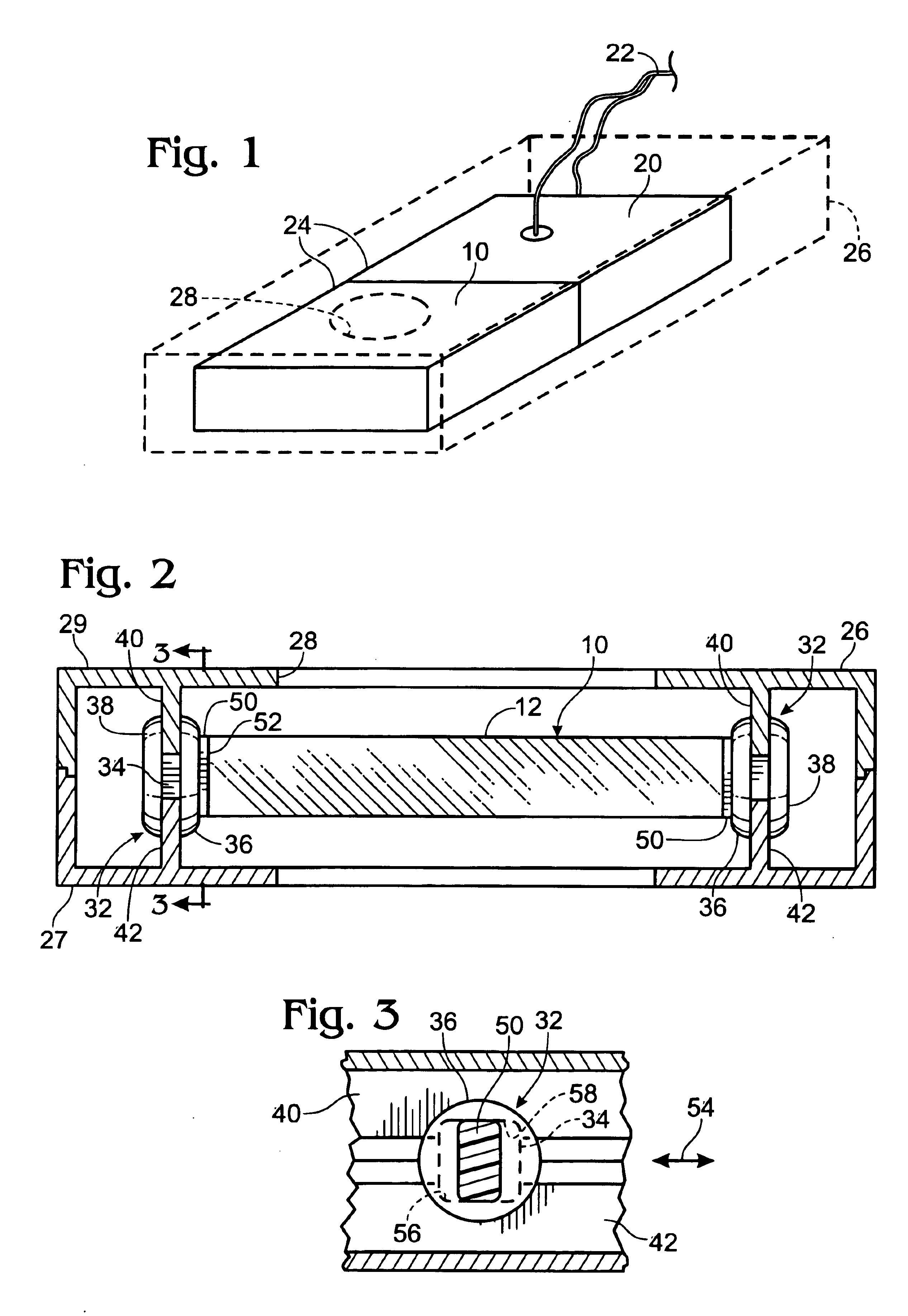
[0026]FIG. 1 depicts the primary components of a photoelastic modulator, including an optical element 10 formed of fused silica. Other material, such as fused quartz calcium fluoride, zinc selenide, silicon and others may be used to form the optical element.

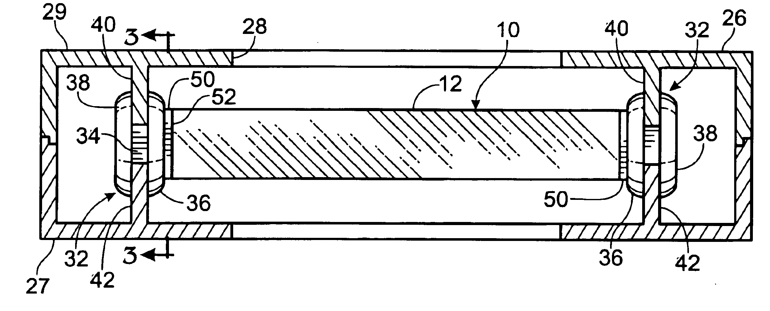
[0027]The optical element 10 is an elongated bar having an entry surface 12 (FIG. 2) against which an incident light wave is directed while the photoelastic modulator is operating. (Other optical element shapes will be acceptable, such as the symmetrical shape depicted in U.S. Pat. No. 3,867,014 to Kemp). A quartz, piezoelectric transducer 20 is bonded to one end of the optical element 10. Electrical leads 22 from the transducer are connected to a driver circuit (not shown) for vibrating the optical element 10. The driver circuit may be tuned to drive the fused-silica element 10 to vibrate at its natural resonant frequency, typically about 50 kHz.

[0028]The optical element 10 and transducer 20 (hereafter collectively referred to a...


PUM

PropertyMeasurementUnit
frequencyaaaaaaaaaa
resonant frequencyaaaaaaaaaa
elastomericaaaaaaaaaa

Abstract

An improved system for mounting an optical assembly of a photoelastic modulator (PEM) to permit free vibration of the optical assembly without introducing any stress or strain on the optical element. Moreover, the mounting system, which includes a mounting block (50), elastomeric mount (32), support flanges (36, 38), and a mounting rail (40), facilitates accurate and easy assembly of the optical element into its enclosure (26).

Description

[0001]This application is a 371 of PCT / US00 / 20165 filed Jul. 25, 2003, which claims benefit of Provisional 60 / 146,616, filed Jul. 30, 1999.TECHNICAL FIELD[0002]This invention relates to a system for mounting an optical assembly of a photoelastic modulator, thereby to facilitate efficient vibration of the optical assembly.BACKGROUND AND SUMMARY OF THE INVENTION[0003]A photoelastic modulator (PEM) is an instrument that is used for modulating the polarization of a beam of light. A PEM employs the photoelastic effect as a principle of operation. The term “photoelastic effect” means that an optical element that is mechanically stressed and strained (deformed) exhibits birefringence that is proportional to the amount of deformation induced into the element. Birefringence means that the refractive index of the element is different for different components of a beam of polarized light.[0004]A PEM includes an optical element, such as fused silica, that has attached to it a transducer for vib...

Claims


Application Information

Patent Timeline
Patent Type & Authority Patents(United States)
IPC IPC(8): G02F1/01G02F1/11G02F1/29G02F1/33
CPCG02F1/0102G02F1/0131G02F2201/503
Inventor SIAHPOUSHAN, MASSOUD
Owner HINDS INSTR
Why Eureka
Try Eureka