
Magnetic disk drive

a magnetic disk drive and magnetic technology, applied in the direction of maintaining head carrier alignment, recording information storage, instruments, etc., can solve the problems of reducing the electric reducing the efficiency and reducing the amount of inertia loss and rotatory motion energy of the disk, so as to reduce the amount of inertia loss and rotatory motion energy, the effect of reducing the power consumption of the magnetic disk driv

Inactive Publication Date: 2005-06-14
HITACHI GLOBAL STORAGE TECH JAPAN LTD
View PDF13 Cites 5 Cited by
  • Summary
  • Abstract
  • Description
  • Claims
  • Application Information

AI Technical Summary

Benefits of technology

[0013]To achieve a reduction in power consumption of the magnetic disk drive and to maintain data access performance, there is a method for reducing the amount of inertia loss and rotatory motion energy of the disk by employing a disk having a small diameter of less than 48 mm or a disk having a thin substrate of less than 0.5 mm. By employing this method, since a disk spin-up time is reduced enormously, despite halting of the disk rotation frequently, negative influences on the access performance can be decreased and a great effectiveness can be achieved in reducing the power consumption of the disk drive. However, a disk having a small diameter and a thin substrate has a disadvantage in that the storage capacity is reduced since the data area is decreased and there is a deterioration in the head positioning accuracy.
[0014]From the aforementioned points of view, the invention achieves reduction in power consumption of the magnetic disk drive through a stand-by function, and maintains access performance while avoiding reduction in memory capacity
[0015]An object of the present invention is to provide a magnetic disk drive in which the time for executing a read command is shorter than the time for executing a write command, as measured from the receipt of the read command or the write command when the magnetic disk drive is in a condition in which the spindle motor is halted.
[0021]In particular, disk access performance can be maintained for the read command execution at the mode 1 normal speed and during the speed-up from the mode 1 to the mode 2 normal operation rotation speed. Specifically, the data read operation can be performed by making the rotatory acceleration during speed-up from the mode 1 to the mode 2 normal operation rotation speed smaller than that at the time of speed-up from where the spindle motor is halted to the mode 1 or the mode 2 normal operation rotation speed.

Problems solved by technology

Therefore, when an automatic power down sequence is in operation and a spindle motor is halted, despite the write command execution or the read command execution of a small number of sectors, a time of about a second is required and deterioration in the performance of the disk drive results.
However, the upper limit of electric power consumed by the magnetic disk drive is often restricted in a portable PC and the electric power applied to the spindle motor cannot be increased.
However, a disk having a small diameter and a thin substrate has a disadvantage in that the storage capacity is reduced since the data area is decreased and there is a deterioration in the head positioning accuracy.

Method used


Image

  • Magnetic disk drive
  • Magnetic disk drive
  • Magnetic disk drive

Examples


Embodiment Construction

[0041]A description will be given of the present invention by reference to the accompanying drawings.

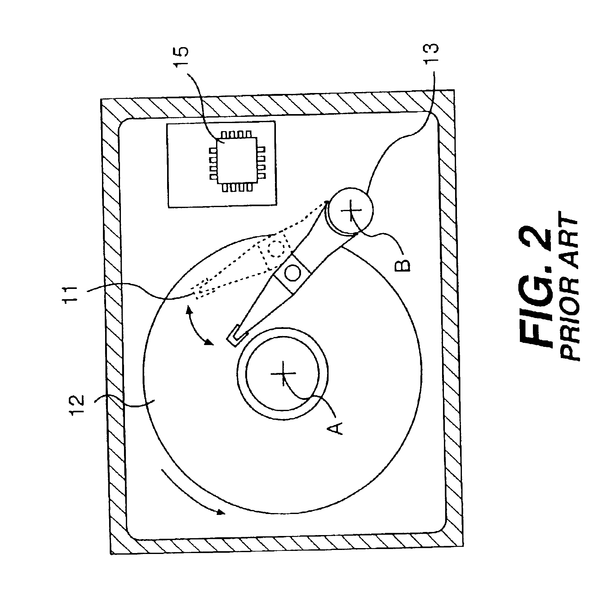
[0042]The basic configuration of the magnetic disk drive of the present invention has the same features as described in the aforementioned conventional art with reference to by using FIGS. 1, 2 and 3. Further, the configuration of the invention has a function for reducing an average power consumption by automatically transitioning to a stand-by status as shown in the conventional art of FIG. 4.

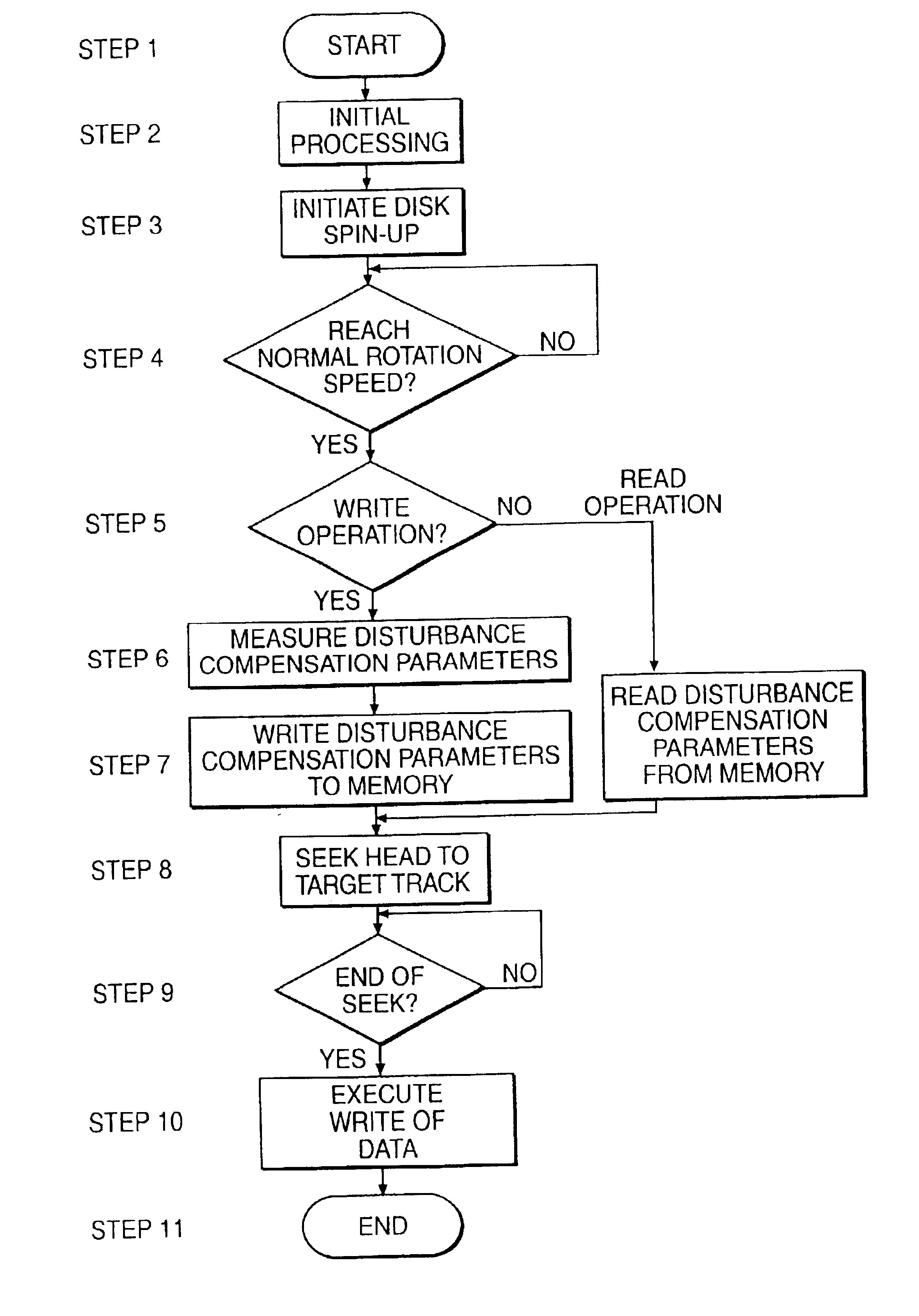
[0043]FIG. 6 describes the operation of the disk drive following receipt of a read or a write command to an end of the read or write operation starting from a stand-by status according to an example of the present invention. In FIG. 6, prior to a time 0, a disk is halted because a magnetic disk drive is in the stand-by status and the speed of rotation at this status is 0 RPM. FIG. 7 shows a flow chart indicating each step in the flow of write and read operations for each process executed by a m...


PUM

PropertyMeasurementUnit
diameteraaaaaaaaaa
timeaaaaaaaaaa
diameteraaaaaaaaaa

Abstract

A magnetic disk drive has a low power consumption state in which the spindle motor is stopped for reducing the average power consumption when no read or write commands have been received. When a read or write command is received, the spindle motor is started. The time it takes to complete a read command is shorter than that for a write command as measured from the receipt of the read command or write command with the spindle motor stopped in the low power consumption state.

Description

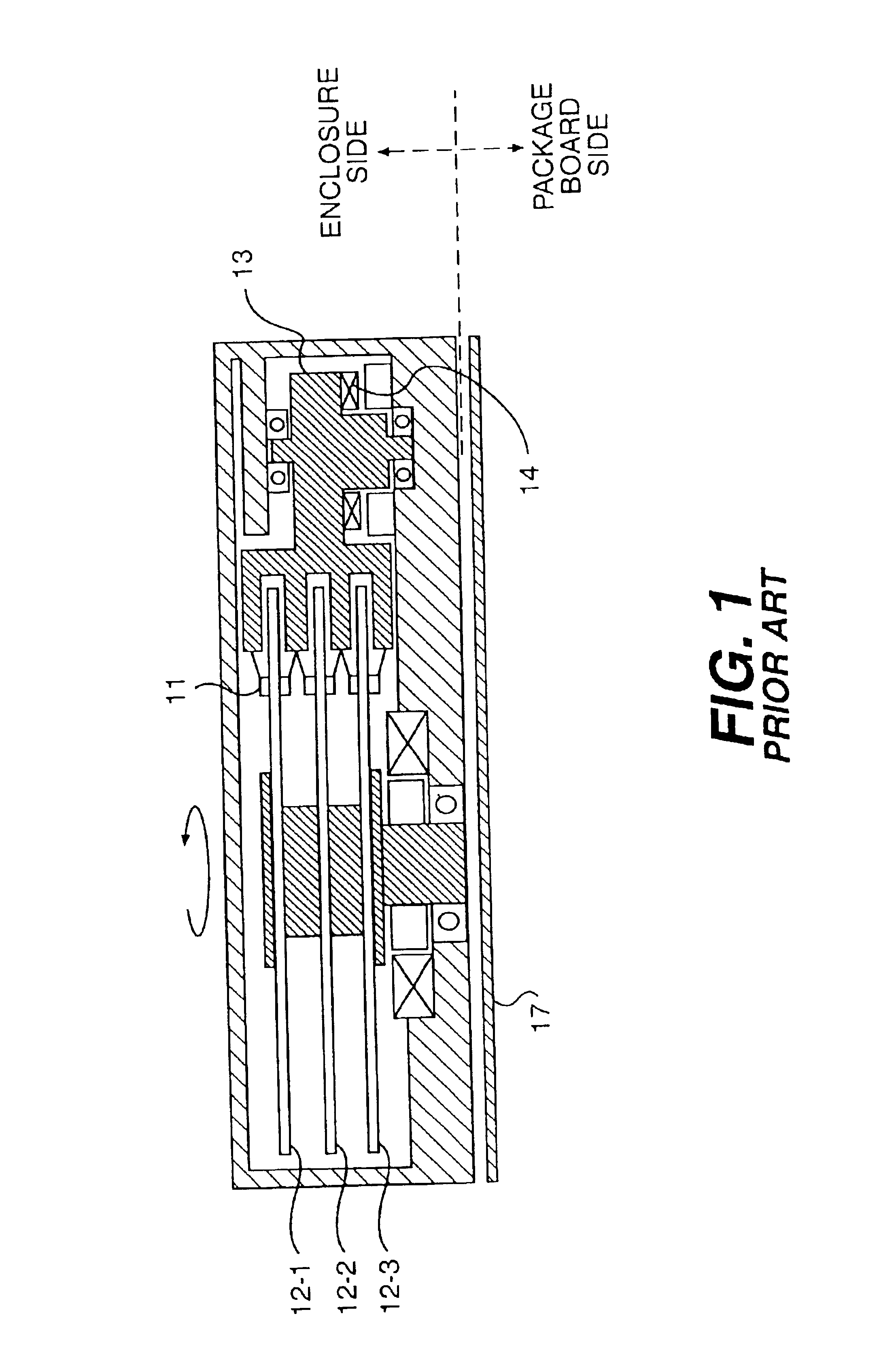
[0001]This is a continuation application of U.S. Ser. No. 09 / 376,354 filed Aug. 18, 1999 now U.S. Pat. No. 6,515,817.BACKGROUND OF THE INVENTION[0002]1. Field of the Invention[0003]The present invention relates to a magnetic disk drive in which the rotation of the spindle motor is halted or stopped for the purpose of achieving lower power consumption. In particular, the invention relates to a magnetic disk drive for reducing the recovery time from the stopped or halted condition of the spindle motor to a rotational speed at which read and write can be performed.[0004]2. Description of the Related Art[0005]A head of a magnetic disk drive moves in the radial direction during rotation of the disk, and is accurately positioned to a target data track for performing read and write of information magnetically. FIG. 1 shows a sectional diagram of the configuration of a typical magnetic disk drive, which includes six heads 11, three disks 12-1, 12-2, 12-3 and a rotary actuator 13 that are st...

Claims


Application Information

Patent Timeline
Patent Type & Authority Patents(United States)
IPC IPC(8): G11B33/12G11B25/04G11B5/55G11B19/20G11B19/00G11B21/08
CPCG11B5/5521G11B33/121G11B25/043
Inventor HAMAGUCHI, TAKEHIKOTAKANO, HISASHITOMIYAMA, FUTOSHIMATSUSHITA, TORU
Owner HITACHI GLOBAL STORAGE TECH JAPAN LTD
Learn More