Capturing images of moving objects with a moving illumination point source

a technology of moving objects and illumination points, applied in the field of optical imaging, can solve the problems of insufficient intensity of illumination provided by the illumination source insufficient light intensity to allow short exposure times to be used, and highly undesirable to start and stop the object during imaging, etc., to achieve the effect of increasing the throughput of the imaging system, reducing the blurring, and reducing the blurring

Inactive Publication Date: 2005-06-14
AGILENT TECH INC
View PDF15 Cites 13 Cited by
  • Summary
  • Abstract
  • Description
  • Claims
  • Application Information

AI Technical Summary

Benefits of technology

[0006]The present invention provides an imaging system that is capable of capturing images of a moving object with minimal blurring by moving a point source of illumination such that the position from which illumination is projected is changed as the object moves to ensure that the position of the image projected onto an imaging plane remains substantially effectively stationary. The position from which illumination is projected functions as a point source of illumination. An image sensor of the imaging system is positioned in the imaging plane and receives illumination projected from the position of the illuminat

Problems solved by technology

The general problem of imaging an object in motion is a result of the time of the exposure and the apparent motion in the focal plane.
However, there are a number of cases where shortening the exposure time or reducing the velocity of the object are not adequate solutions to the problem of blurring, particularly in industrial imaging.
For example, in many situations the object velocity may be fixed, or the intensity of the illumination provided by the illumination source may be insufficient to allow short expo

Method used


Image

  • Capturing images of moving objects with a moving illumination point source
  • Capturing images of moving objects with a moving illumination point source
  • Capturing images of moving objects with a moving illumination point source

Examples


Embodiment Construction

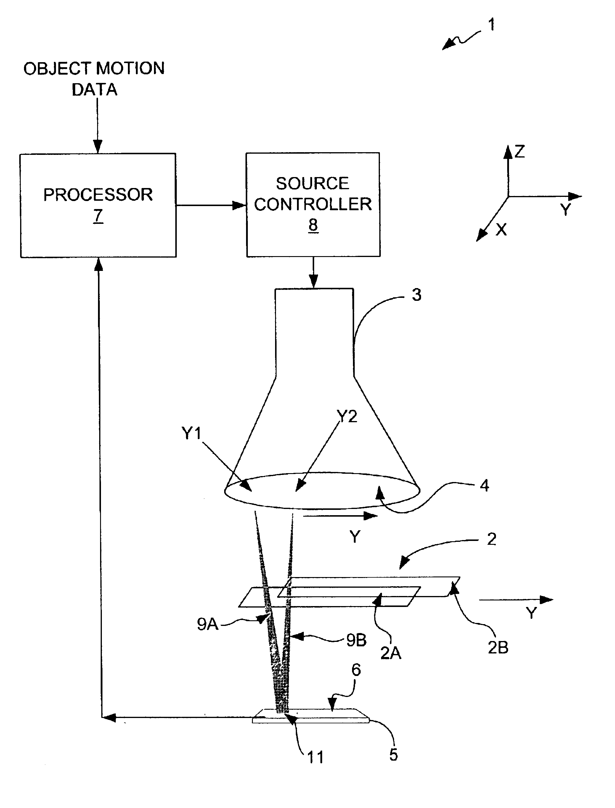
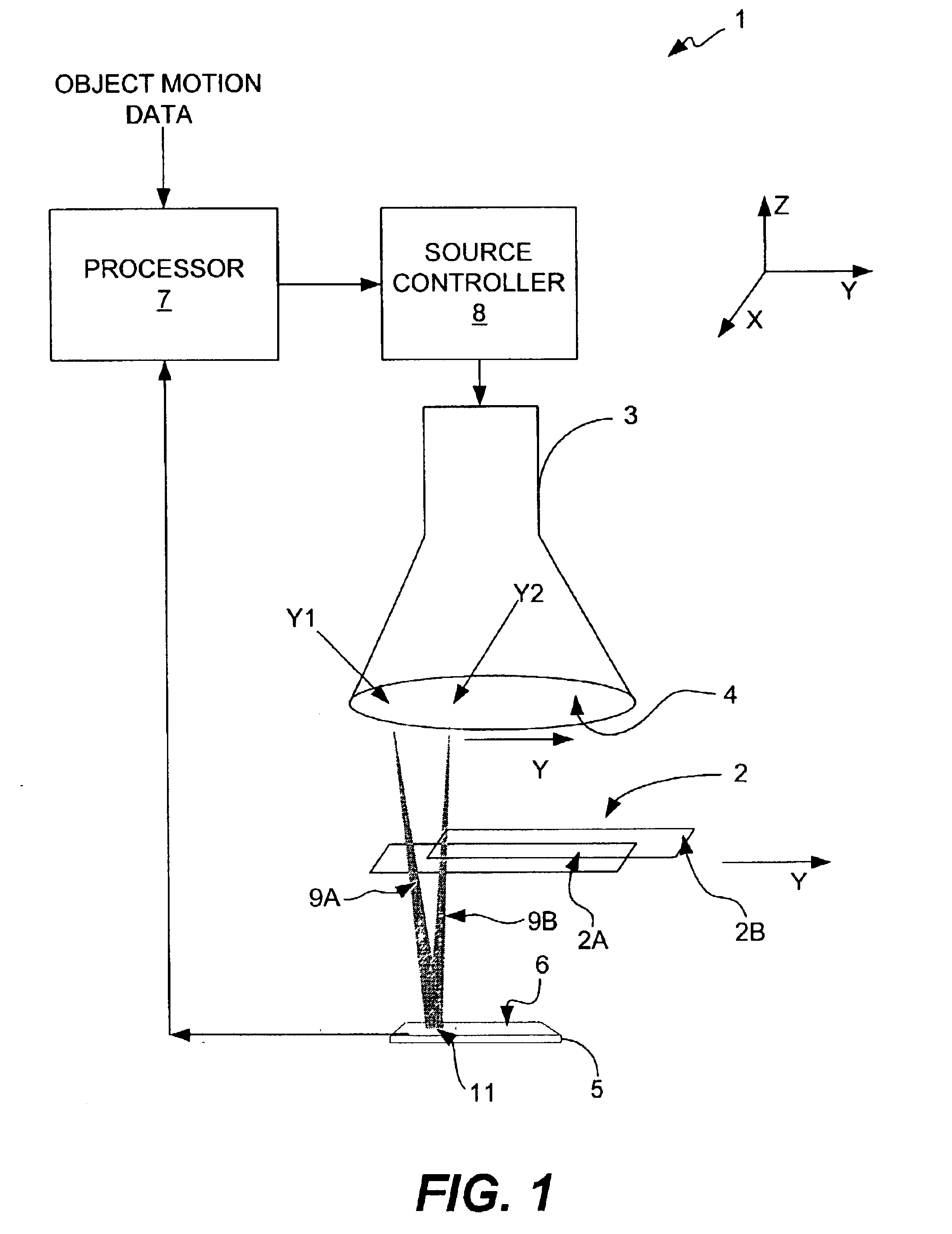
[0013]The present invention is directed to projection imaging of an object with a point source of illumination where the location of the point source is addressable, or able to be electrically positioned, in at least one and, in applications in which three-dimensional imaging is performed, in two dimensions. A point source of illumination is defined as a region in space that is comparable to or smaller in dimensions than the imaging resolution desired from the system from which radiation of any form that is used in imaging can be projected. Such radiation can be any radiation that travels in straight lines and interacts with an object, thereby resulting in a change in the nature of the radiation in some form that can represent a property of the object. The radiation could be x-ray radiation, visible light radiation, infrared or ultraviolet radiation, other electromagnetic radiation, such as radio waves or terahertz radiation. The radiation could also be acoustic radiation, for examp...


PUM


Abstract

An imaging system that is capable of capturing images of moving objects as they are moving with minimal blurring by moving a point source of illumination such that the position from which illumination is projected is changed as the object moves to ensure that the position of the image projected onto an imaging plane remains substantially effectively stationary. The position from which illumination is projected functions as a point source of illumination. A image sensor of the imaging system is positioned in the imaging plane and receives illumination projected from the position of the illumination source that passes through the moving object. The image sensor produces electrical signals in response to the received illumination. Because the image of the moving object remains effectively stationary on the image sensor, which is located in the imaging plane, an image of at least a portion of the moving object can be constructed with minimal blurring and without having to halt the object to capture an image of it. Because it is not necessary to halt the object and allow the object to settle before capturing an image of it, the throughput of the imaging system is increased and the captured images are greatly improved.

Description

BACKGROUND OF THE INVENTION[0001]The present invention relates to optical imaging. More particularly, the present invention relates to capturing images of moving objects by moving the point source of illumination generally synchronously with the motion of the object to prevent or minimize blurring of the captured images while, at the same time, increasing the throughput of the imaging process.[0002]In the field of high-speed industrial imaging, it is desirable to maintain objects in motion at constant velocity in order to maximize the throughput of the production line. Imaging techniques in which imaging is performed by transmission of illumination through an object to a detector, such as in x-ray radiography, are commonly referred to as projection imaging techniques. The images captured during imaging are referred to as projection images. The general problem of imaging an object in motion is a result of the time of the exposure and the apparent motion in the focal plane. In general...

Claims


Application Information

Patent Timeline
IPC IPC(8): G01N23/04G01N23/02
CPCG01N23/04G01N23/044
Inventor ROSNER, S. JEFFREYCHOPRA, NASREEN GAZALASHIH, ANG
Owner AGILENT TECH INC
Why Eureka
Try Eureka