Base station for a wireless local area network, wireless terminal and program thereof

a wireless local area network and wireless terminal technology, applied in the direction of data switching networks, synchronisation arrangements, assess restrictions, etc., can solve the problems of qos (quality of service) improvement of such wireless lan qos to be degraded

Active Publication Date: 2005-06-14
NEC CORP
View PDF9 Cites 39 Cited by
  • Summary
  • Abstract
  • Description
  • Claims
  • Application Information

AI Technical Summary

Benefits of technology

[0010]By classifying priority of data finely compared with the prior art for every application, probability of simultaneous reception of different data having same priority in the base station is reduced and only same data are buffered in the first buffer means. By transmitting the same data buffered in the first buffer means at a constant interval, the data is received at a constant interval by the wireless terminal.
[0014]Further, the transmission control means may include means for transmitting data buffered in the respective first buffer means according to a predetermined order of the first buffer means. By setting the transmission sequence on the basis of the data transmission time, it is possible to reduce time for which priority data can not be transmitted during the time period from the transmission time of a beacon signal to the transmission of a next beacon signal.
[0020]The judge control means may include means, which, when data having priority registered in the priority table is received, produces the first buffer means corresponding to that priority, and means, when data having priority corresponding to the first buffer means is not received for a predetermined time, deletes the first buffer means. By allowing only the first buffer means corresponding to the necessary priority to produce continuously, it is possible to effectively utilize a memory capacity of the first buffer means.
[0022]The base station may further include transmission time regulation means for monitoring a transmission time of data transmitted from the transmission control means and, when a transmission time of data buffered in the second buffer means is shorter than a predetermined time, instructing the transmission control means of shortening of a transmission time of data buffered in the first buffer means. In such case, it is possible to prolong the transmission time of data buffered in the second buffer means.
[0031]In the base station, the table memory means further stores a beacon interval table for corresponding header value of data with the interval between beacon signals. The judge control means may include means for detecting the header value of the received data and, when the detected header value exists in the beacon interval table, reading an interval corresponding to the detected header value and outputting the latter to the beacon signal producing means. The beacon signal producing means may include means for changing the interval of the beacon signal to an interval inputted from the judge control means. By changing the beacon signal interval correspondingly to data compression rate, it is possible to eliminate a break of data when the compressed data is expanded in the receiving terminal.
[0047]In the latter case, since the back-off time in transmitting the data having priority set is shortened, transmission of data having priority set can be expedited.

Problems solved by technology

In order to realize frequency band width and delay required by users and applications, an improvement of QoS (Quality of Service) of such wireless LAN is an important problem.
As a result, delay of data reception in the wireless terminal is varied, causing QoS to be degraded.
Further, since the conventional wireless terminal has no function of setting priority of data and transmitting it with the priority set by the base station, an amout of delay of data is varied when data is transmitted from the wireless terminal to the base station or when data are transmitted and received within the wireless terminal, causing QoS to be degraded.

Method used


Image

  • Base station for a wireless local area network, wireless terminal and program thereof
  • Base station for a wireless local area network, wireless terminal and program thereof
  • Base station for a wireless local area network, wireless terminal and program thereof

Examples


first embodiment

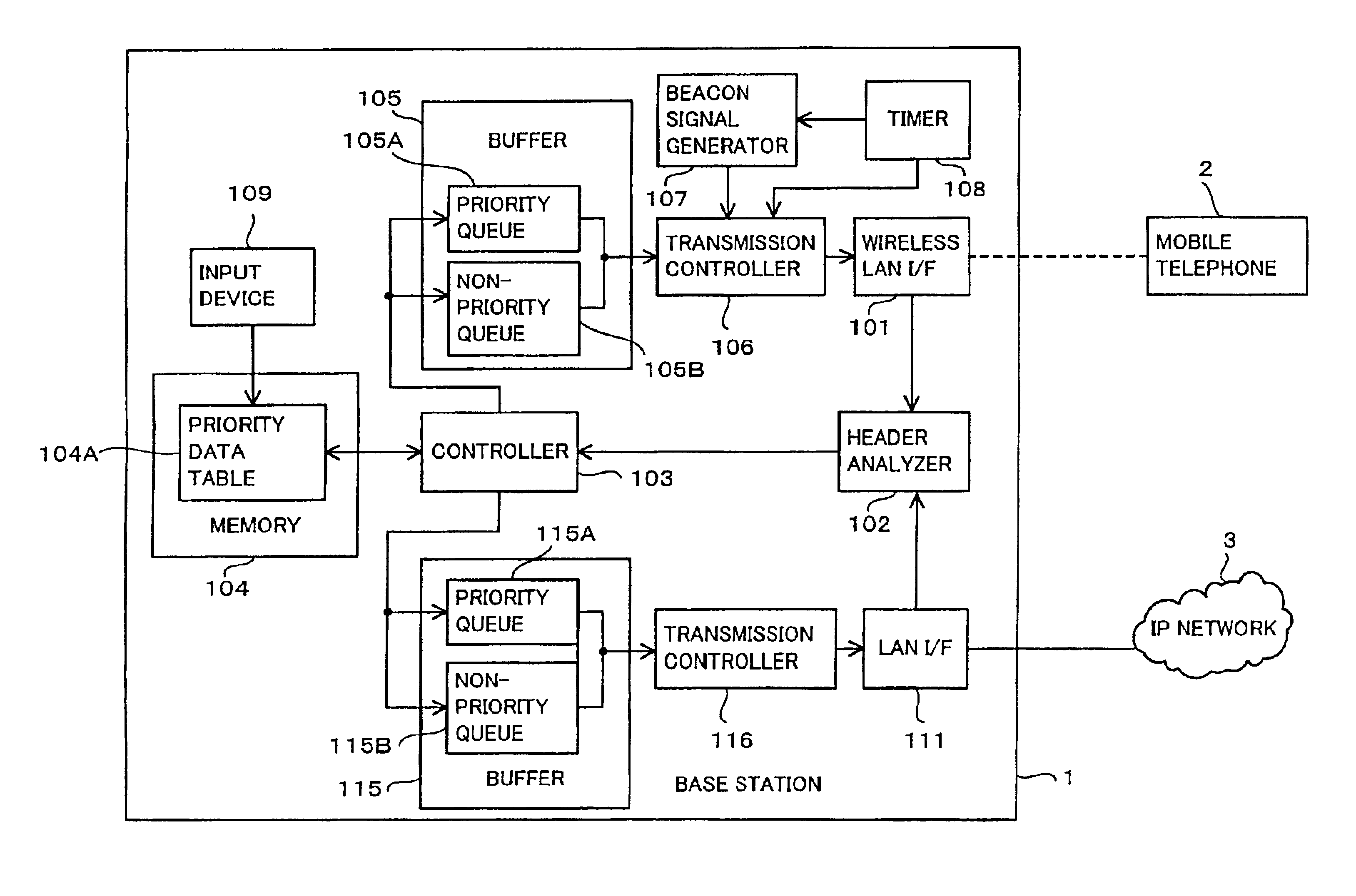
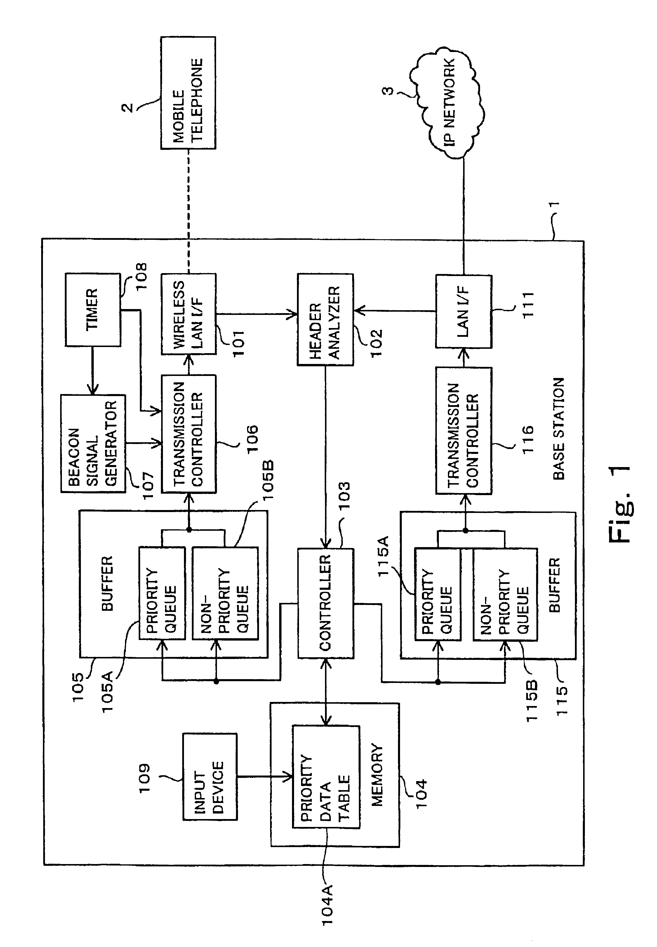
[0065]FIG. 1 is a block diagram showing a construction of a base station according to the first embodiment of the present invention. In FIG. 1, a base station 1 includes a wireless LAN interface 101, a header analyzer 102, a controller 103, a memory 104, a buffer 105, a transmission controller 106, a beacon signal generator 107, a timer 108, an input device 109, a LAN interface 111, a buffer 115 and a transmission controller 116.

[0066]The wireless LAN interface 101 is an interface between the base station 1 and a mobile telephone 2 to perform a data exchange between them through a wireless LAN 4. The wireless LAN is a radio communication system exemplified by IEEE 802.11 and is not specified in the present invention.

[0067]The header analyzer 102 analyzes data received by the wireless LAN Interface 101 and outputs a result of analysis to the controller 103. In more detail, the header analyzer 102 analyzes an information contained in a header of the received data such as physical laye...

second embodiment

[0091]FIG. 4 is a block diagram showing a construction of a portion of a base station according to a second embodiment of the present invention. The base station shown in FIG. 4 includes, in lieu of the buffer 105 in the first embodiment, a buffer 305 having a plurality of priority queues 1051 to 105n, where n is an integer equal to or larger than 2. When the priority includes 2 or more orders, each of the priority queues 1051 to 105n buffers a priority data of every priority. By providing the priority queues 1051 to 105n in such manner, it is possible, even when a plurality of priority data are received simultaneously by the base station 1, to transmit these data to the respective mobile telephones at the constant interval T. Therefore, the radiotelephones can receive the message data at the constant interval T.

[0092]In this case, the transmission controller 106 transmits buffered data to the priority queues 1051 to 105n in time periods, which are prelimiarily set correspondingly t...

third embodiment

[0101]FIG. 5 is a block diagram showing a construction of a base station according to a third embodiment of the present invention. The base station 1A shown in FIG. 5 is featured by that a packet shredder (data size regulator means) 121 and a transmission time monitor 122 are added to the base station 1 shown in FIG. 1.

[0102]The packet shredder 121 functions to regulate the data outputted from the controller 103 to a predetermined size and to output the size regulated data to the priority queue 105A or the non-priority queue 105B. With this construction of the base station, it is possible, even when the data size is too large to transmit it within the time between adjacent beacon signals, to standardize the data size by using the packet shredder 121 to thereby transmit it within the time between adjacent beacon signals. Therefore, it is possible to transmit data at constant interval regardless of the original size thereof.

[0103]The transmission time monitor (transmission time regula...


PUM


Abstract

A base station comprises table memory elements 104 for storing a priority data table 104A indicative of priorities of data set for every application, judge control elements 103 for judging priority of received data on the basis of the priority table and outputting data whose priorities are set to first buffer elements 105A and the data whose priorities are not set to second buffer elements 105B, beacon signal transmission elements for transmitting a beacon signal at a constant interval and transmission control elements 106 for transmitting the data buffered in the first buffer elements to a destination at a constant interval by using the beacon signal as a reference and, after the data buffered in the first buffer elements is transmitted, transmitting the data buffered in the second buffer elements to a destination.

Description

BACKGROUND OF THE INVENTION[0001]1. Field of the Invention[0002]The present invention relates to a base station for a wireless local area network (LAN) and a wireless terminal connected to the base station through the wireless LAN and a computer program for realizing functions of the base station or the wireless terminal.[0003]2. Description of the Related Art[0004]LAN had been developed and has been utilized as a wired network initially. However, with the recent increase of operating speed thereof and the recent progress of mobile computing technology and mobile terminal, a wireless LAN having at least a portion thereof constructed with a wired network has been developed and utilized popularly.[0005]In order to realize frequency band width and delay required by users and applications, an improvement of QoS (Quality of Service) of such wireless LAN is an important problem. In view of this, a system in which a base station sets eight priority steps from step 0 to step 7 corresponding...

Claims


Application Information

Patent Timeline
Patent Type & Authority Patents(United States)
IPC IPC(8): H04L12/56H04L12/28H04L29/06H04W28/02H04W28/14H04W48/08H04W56/00H04W72/04H04W72/10H04W72/12H04W74/04H04W84/12H04W88/08H04W92/10H04W92/20
CPCH04L47/10H04L47/14H04L47/2408H04L47/2433H04L47/2475H04L47/6215H04W72/1242H04L49/90H04W88/08H04W28/14H04W48/08H04W56/00H04W84/12H04W28/02H04W72/569H04W8/04
Inventor TSUTSUMI, TAKAYUKIKOBAYASHI, YOSHIKAZU
Owner NEC CORP
Why Eureka
Try Eureka