Multi-station robotic welding assembly

a robotic welding and multi-station technology, applied in the direction of arc welding apparatus, control mechanism, program control, etc., can solve the problem of relative inefficiency of the process, and achieve the effect of increasing production efficiency and labor cos

Inactive Publication Date: 2005-06-14
ADVANCED TUBING TECH
View PDF21 Cites 25 Cited by
  • Summary
  • Abstract
  • Description
  • Claims
  • Application Information

AI Technical Summary

Benefits of technology

[0003]Therefore, it is an object of the invention to provide a multi-station robotic welding assembly which offers increased production efficiency without increased labor cost.
[0005]It is another object of the invention to provide a multi-station robotic welding assembly which can be conveniently relocated without substantially disassembly or breaking down of parts.
[0009]It is another object of the invention to provide a multi-station robotic welding assembly which requires less tooling and tooling costs as compared to standard multi-robot weld cells. In standard cells, two fixtures are generally serviced by a single robot.
[0010]It is another object of the invention to provide a multi-station robotic welding assembly including multiple robots which operate in separate and distinct work envelopes which do not cross each other. In standard two-robot systems, the work envelopes cross thus causing longer programming time. The crossing envelopes further increase the risk of the robots crashing into each other as a result of misprogramming.
[0017]According to another preferred embodiment of the invention, the fixture base includes a junction box which connects all indexers and houses an electrical D-ring, or slip ring. Unlike conventional indexers which rotate clockwise and counterclockwise in a 180-degree path, the present D-ring allows continuous 360-degree rotation of the base indexer, thereby avoiding winding and breakage of cables inside the junction box.

Problems solved by technology

The cumulative operator “down time” during the welding process over a given shift is substantial, and results in a relatively inefficient process.

Method used


Image

  • Multi-station robotic welding assembly
  • Multi-station robotic welding assembly
  • Multi-station robotic welding assembly

Examples


Embodiment Construction

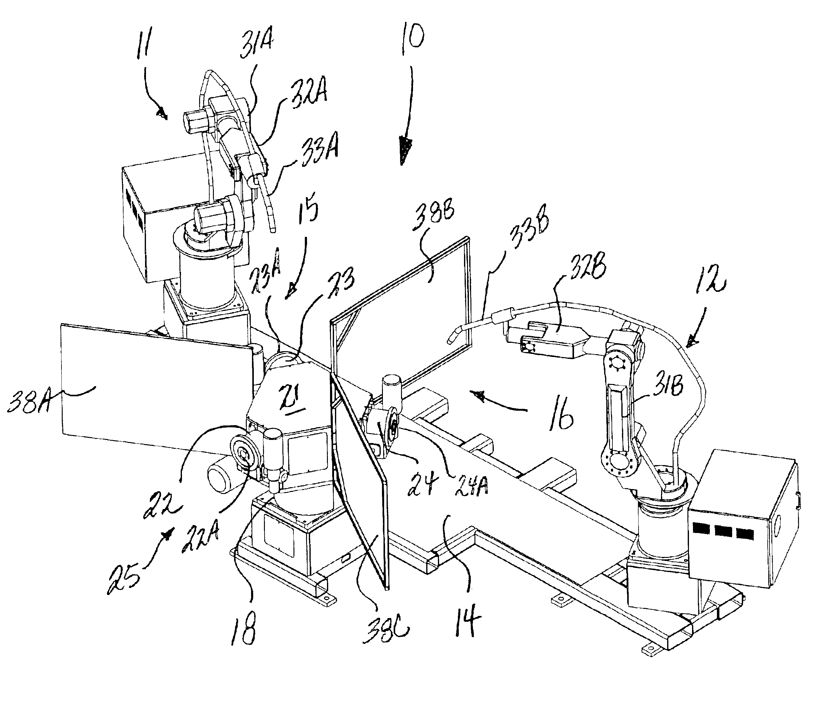
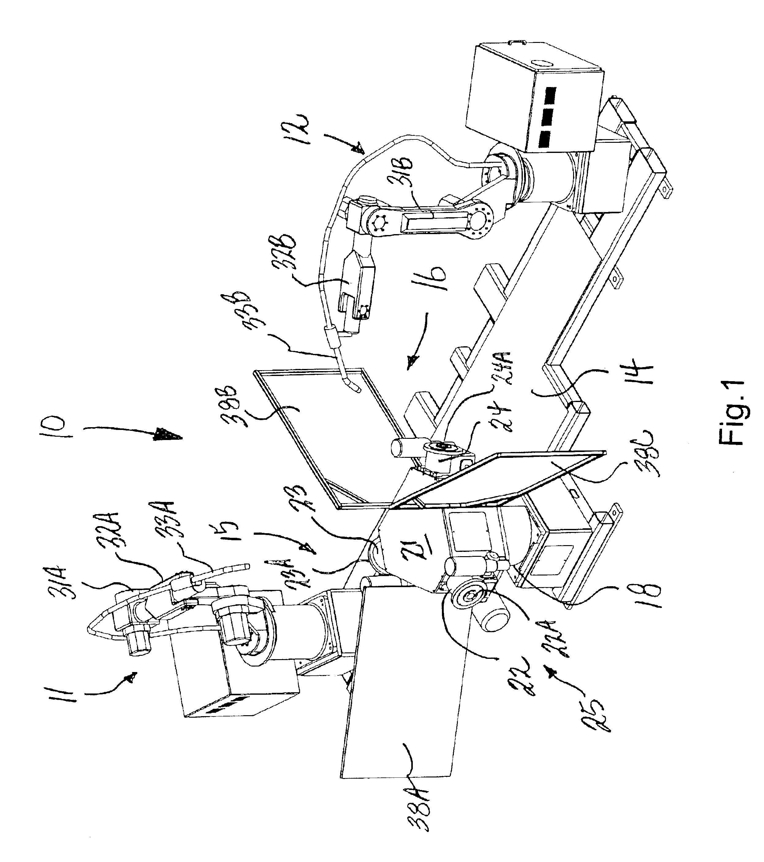
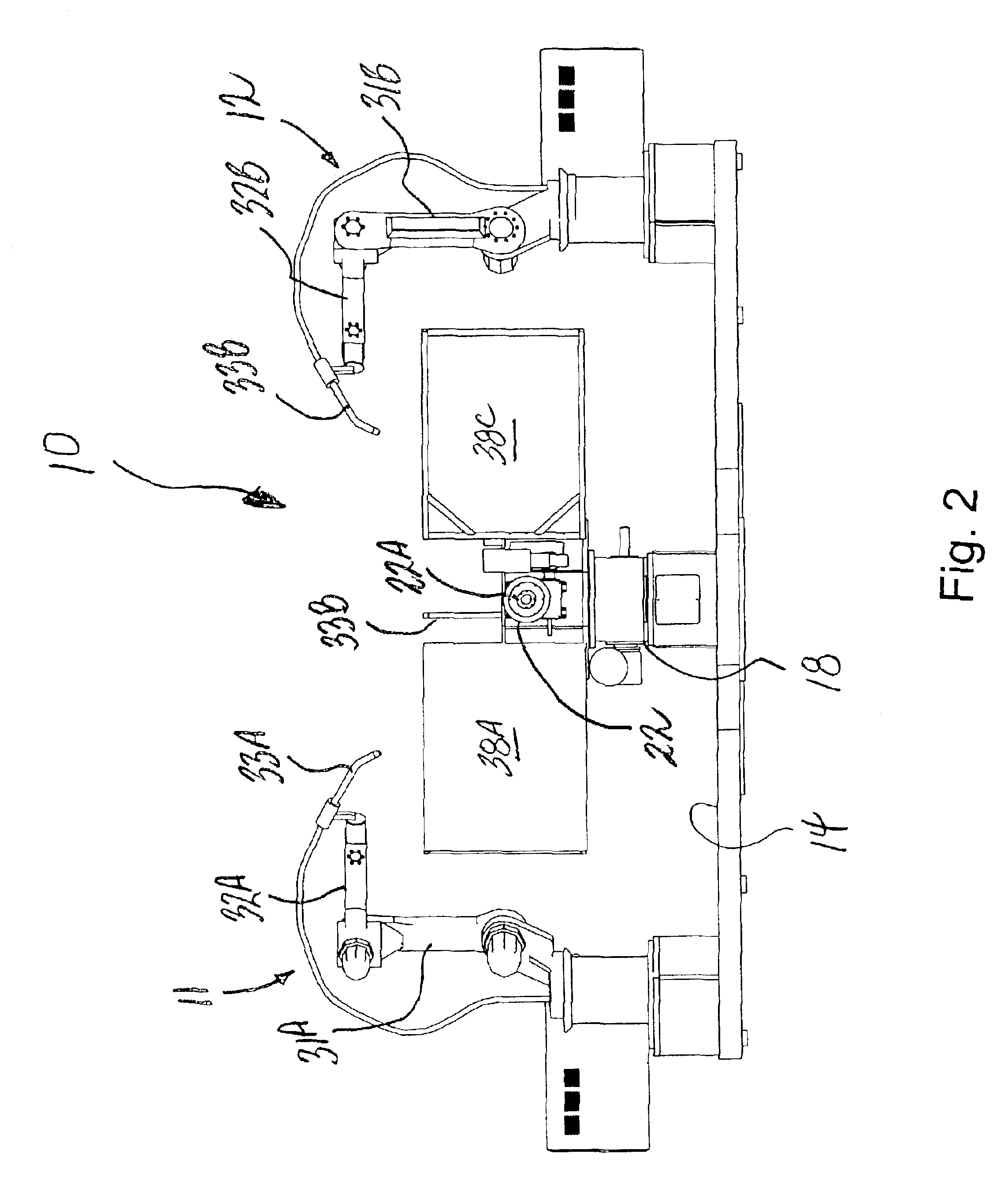
[0030]Referring now specifically to the drawings, a multi-station robotic welding assembly according to the present invention is illustrated in FIGS. 1-3, and shown generally at reference numeral 10. The assembly 10 is especially applicable in a production environment for welding items such as bumpers, foot plates, headlight supports, arm rests, and other components commonly used in all-terrain vehicles (ATVs) and golf carts. The assembly 10 includes first and second arc welding robots 11 and 12 attached to a common mounting platform 14 and located in respective weld stations 15 and 16. A rotatable fixture base 18 is mounted to the platform 14 between the robots 11, 12, and includes a junction box 21 and three indexers 22, 23, and 24 adapted for carrying respective fixtures used for holding workpieces to be welded. The fixtures “F” and “W” are illustrated in FIGS. 4-8, discussed below. Each fixture is custom designed and secured directly to a face plate 22A, 23B, and 24A of the inde...


PUM

PropertyMeasurementUnit
welding voltageaaaaaaaaaa
currentaaaaaaaaaa
electric poweraaaaaaaaaa

Abstract

A multi-station robotic welding assembly includes a mounting platform, and a plurality of robots attached to the mounting platform and located in respective weld stations. Each of the robots includes an elongated movable arm and wrist. A welding torch is attached to each of the robots, and is adapted for being manipulated by the movable arm and wrist. A rotatable fixture base is located on the mounting platform, and is adapted for supporting a plurality of fixtures. Each of the fixtures is adapted for holding and positioning a workpiece for welding in respective weld stations. A base indexer is adapted for repeatedly rotating the fixture base by a predetermined degree, such that the fixtures are positioned within respective weld stations for an index interval sufficient to complete welding of the workpieces.

Description

TECHNICAL FIELD AND BACKGROUND OF INVENTION[0001]This application relates to a multi-station robotic welding assembly. The invention utilizes two or more industrial robots each including a welding torch at a distal end of a movable arm and wrist. Welding is carried out by moving the welding torch along a taught path relative to a workpiece. When a welding operation is started, a preset welding voltage and current are commanded from a robot control device to a controller of a welding machine. On receiving the command, the welding machine supplies electric power between the workpiece and an electrode of the welding torch. When an arc discharge is generated between the workpiece and the electrode, it is detected by the controller of the welding machine, which then supplies an arc generation signal to the robot control device. On receiving the arc generation signal, the robot control device commands welding voltage and current for normal welding to the controller of the welding machine,...

Claims


Application Information

Patent Timeline
Patent Type & Authority Patents(United States)
IPC IPC(8): G06F19/00B23K9/28B23Q11/08B23Q39/04B25J9/00G05B19/418
CPCB23K9/287B23Q11/08B23Q39/044B25J9/0084G05B19/41825B25J9/0096Y10T74/20305G05B2219/39101G05B2219/45104Y02P90/02
Inventor PASSMORE, MICHAEL L.SMYTH, DOUGLAS E.
Owner ADVANCED TUBING TECH
Why Eureka
Try Eureka