Instrument reference flight display system for horizon representation of direction to next waypoint

a flight display and direction technology, applied in the field of instruments reference flight display systems for horizon representation of direction to next waypoint, can solve problems such as difficult safety monitoring of each flight function, and achieve the effects of improving situational awareness, simplifying cockpit scan management, and contributing to visual momentum within the cockpi

Inactive Publication Date: 2005-06-14
HONEYWELL INT INC
View PDF24 Cites 5 Cited by
  • Summary
  • Abstract
  • Description
  • Claims
  • Application Information

AI Technical Summary

Benefits of technology

[0005]The invention of one aspect provides a primary flight display instrument in which a symbol—such as a small star or triangle—indicates the bearing to the current waypoint in the flight navigation plan. In another aspect, the invention provides a display with a bearing indication symbol showing a follow-on waypoint in the flight plan. In the preferred aspect of the invention, one symbol is located on the horizon line of the primary flight display (or the attitude indicator) providing bearing to the current waypoint in the flight plan and/or to the following way

Problems solved by technology

Viewing the separate devices also makes safe

Method used


Image

  • Instrument reference flight display system for horizon representation of direction to next waypoint
  • Instrument reference flight display system for horizon representation of direction to next waypoint
  • Instrument reference flight display system for horizon representation of direction to next waypoint

Examples


Embodiment Construction

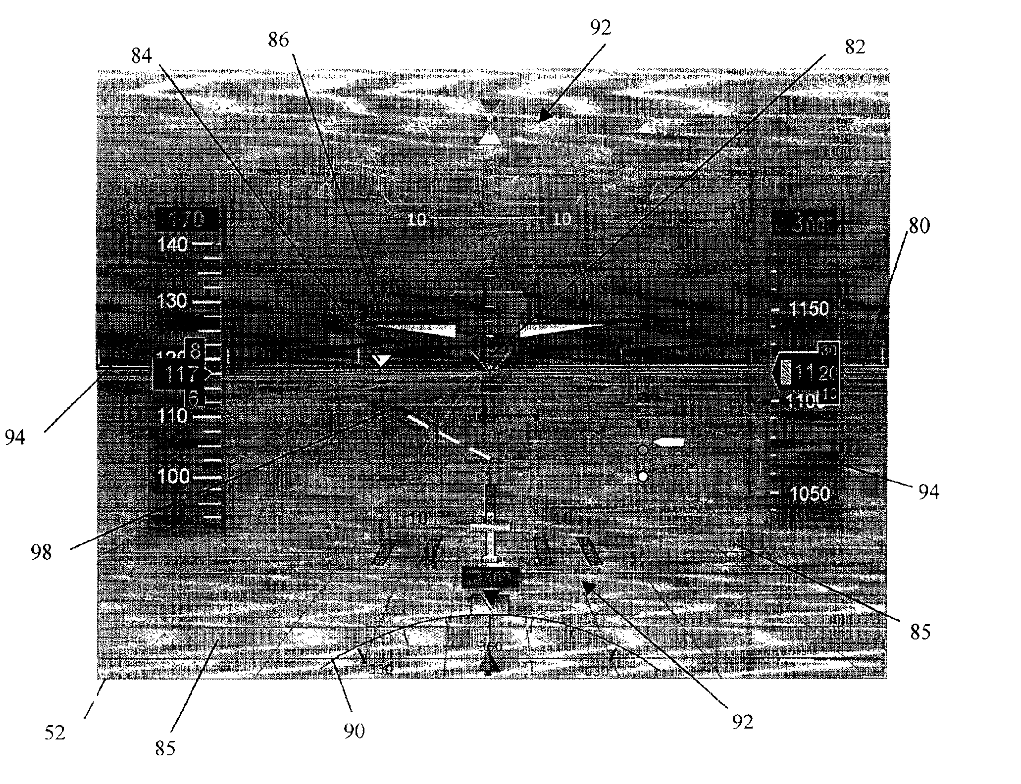
[0022]FIG. 4 shows a system 50 constructed according to the invention; system 50 may reside within an aircraft to generate a flight display 52 for a pilot and to assist that pilot in IMC. An aircraft information collation unit 54 connects to aircraft navigation unit 56 and aircraft attitude and air data unit 58 so as to collate relevant information that may be used to generate display 52. Those skilled in the art should appreciate that units 56, 58 may represent one or more existing aircraft electronic devices or instruments that provide navigation, attitude and air data information; collation unit 54 connects with units 56, 58 through one or more data buses 60.

[0023]In illustrative operation, navigation unit 56 delivers the following data to collation unit 54 over buses 60: the direction to next waypoint over data bus 60A; the information about last waypoint over data bus 60B; and a left / right deviation over data bus 60C. Similarly, in illustrative operation, attitude and air data ...


PUM


Abstract

The invention provides a primary flight display instrument in which a symbol—such as a small star or triangle—indicates the bearing to the current waypoint in the flight navigation plan. The display may also show a bearing indication symbol showing a follow-on waypoint in the flight plan. These symbols are preferably located on the horizon line of the primary flight display (or the attitude indicator) providing bearing to the current waypoint in the flight plan and/or to the following waypoint. An image processing unit generates the display, including earth ground and horizon, in a view substantially conformal with a VMC view from the aircraft.

Description

CROSS REFERENCE TO RELATED APPLICATION[0001]This application claims the benefit of provisional application No. 60 / 239,721, dated Oct. 11, 2000.BACKGROUND OF THE INVENTION[0002]During visual reference flight (VMC), aircraft pilots often use landmarks (e.g., a mountain peak) on the horizon to help guide them to a destination. Such visual landmarks provide situation awareness. FIG. 1 and FIG. 2 schematically illustrate a pilot 10 viewing a landmark 12 through an aircraft windshield 14 during VMC. As known to those skilled in the art, pilot 10 has a field-of-view 16 defined by windshield 14. Landmark 12 is illustratively shown as a city located at the horizon 18 of ground 20 as viewed from pilot 10. In FIG. 2, earth's ground 20 is shown illustratively as grid lines 22 to provide a perspective view that a distant ground object (e.g., a ground square 24) is smaller than a closer ground object of the same size (e.g., a ground square 26).[0003]When flying under instrument reference flight (...

Claims


Application Information

Patent Timeline
IPC IPC(8): G01C23/00
CPCG01C23/005
Inventor CUNDIFF, CHAD L.
Owner HONEYWELL INT INC
Why Eureka
Try Eureka