Supercharge Your Innovation With Domain-Expert AI Agents!

Fan shroud with internal aspirator

a fan shroud and aspirator technology, applied in the field of aspirators, can solve the problems of raising the cost of the muffler and/or the exhaust pipe, and raising the noise level

Inactive Publication Date: 2005-06-21
DEERE & CO
View PDF2 Cites 11 Cited by
  • Summary
  • Abstract
  • Description
  • Claims
  • Application Information

AI Technical Summary

Benefits of technology

The invention provides a fan shroud with an integrated aspirator for a work vehicle pre-cleaner. The fan shroud has an aspirator portal in the upper surface, an aspirator with an air intake and an air outlet, and an aspirator hose connected to the pre-cleaner and the fan. The vacuum necessary for proper aspiration is achieved by air movement, induced by the fan, between the air intake of the pre-cleaner and the aspirator via the aspirator port and the aspirator hose. The invention provides a compact and space-saving solution for providing aspiration to the pre-cleaner without the need for additional hoses or fittings.

Problems solved by technology

An exhaust system aspirator, however, creates a restriction in the engine exhaust, raises noise levels and raises the cost of the muffler and / or exhaust pipe.

Method used


Image

  • Fan shroud with internal aspirator
  • Fan shroud with internal aspirator
  • Fan shroud with internal aspirator

Examples


Embodiment Construction

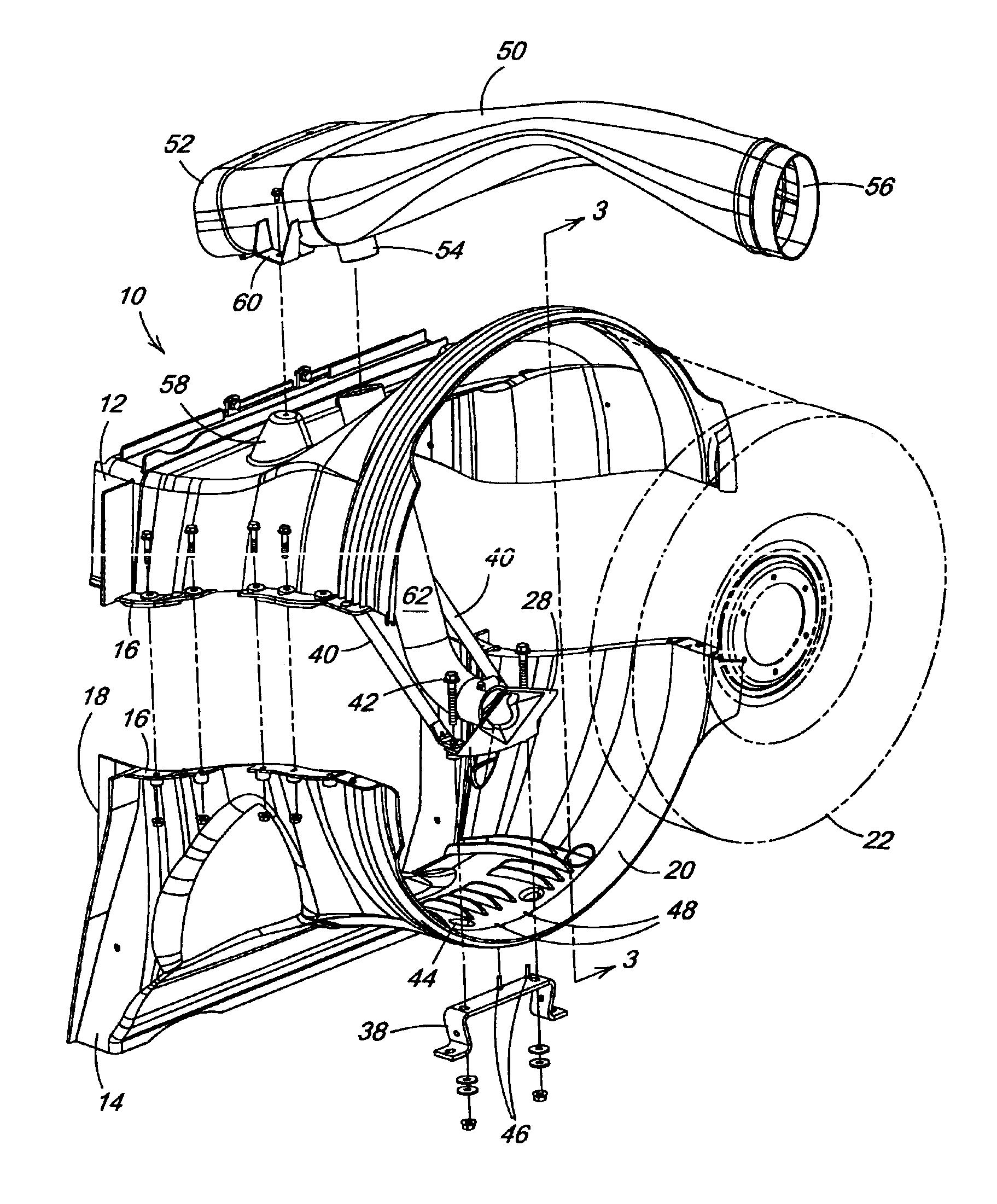
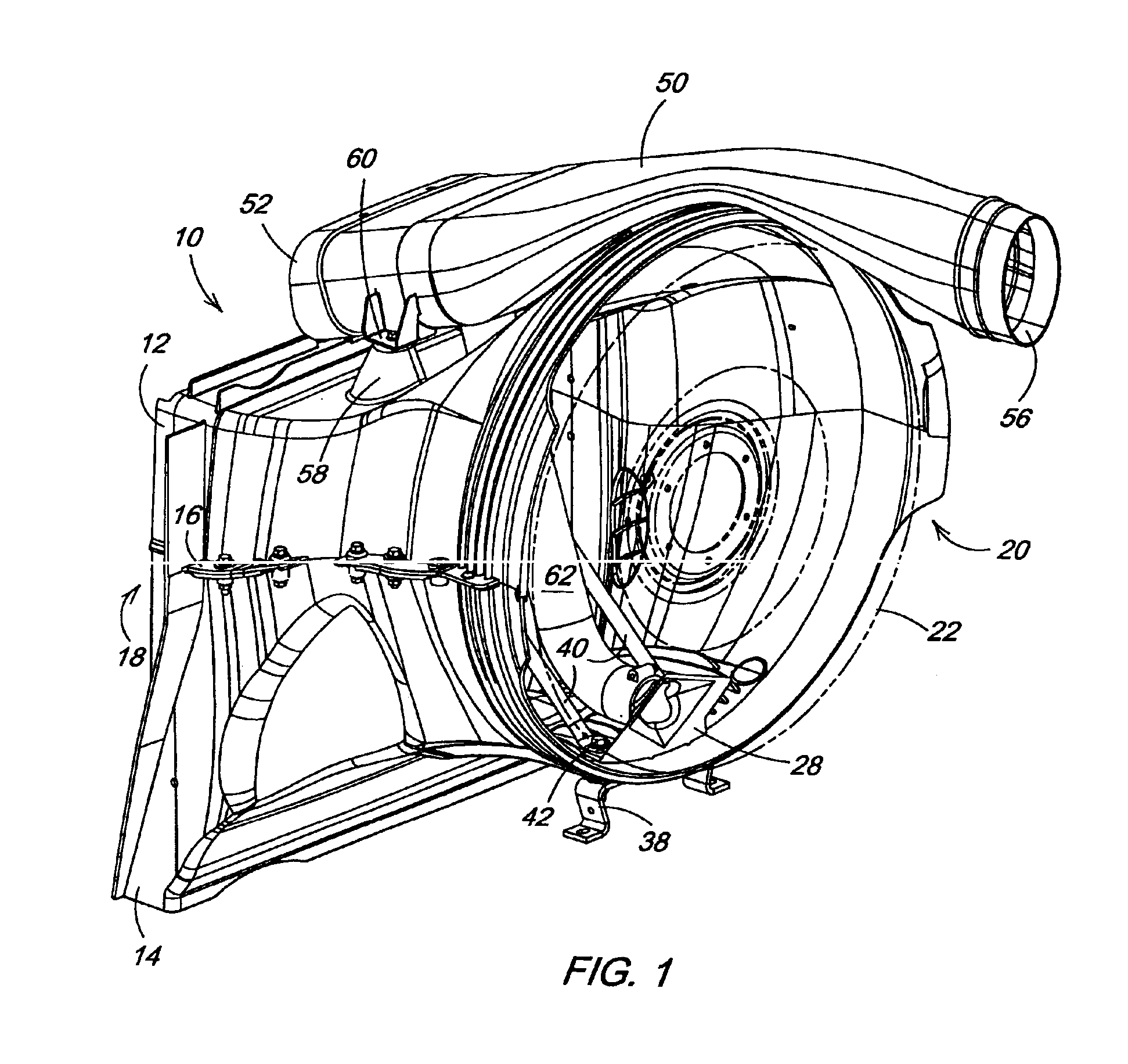
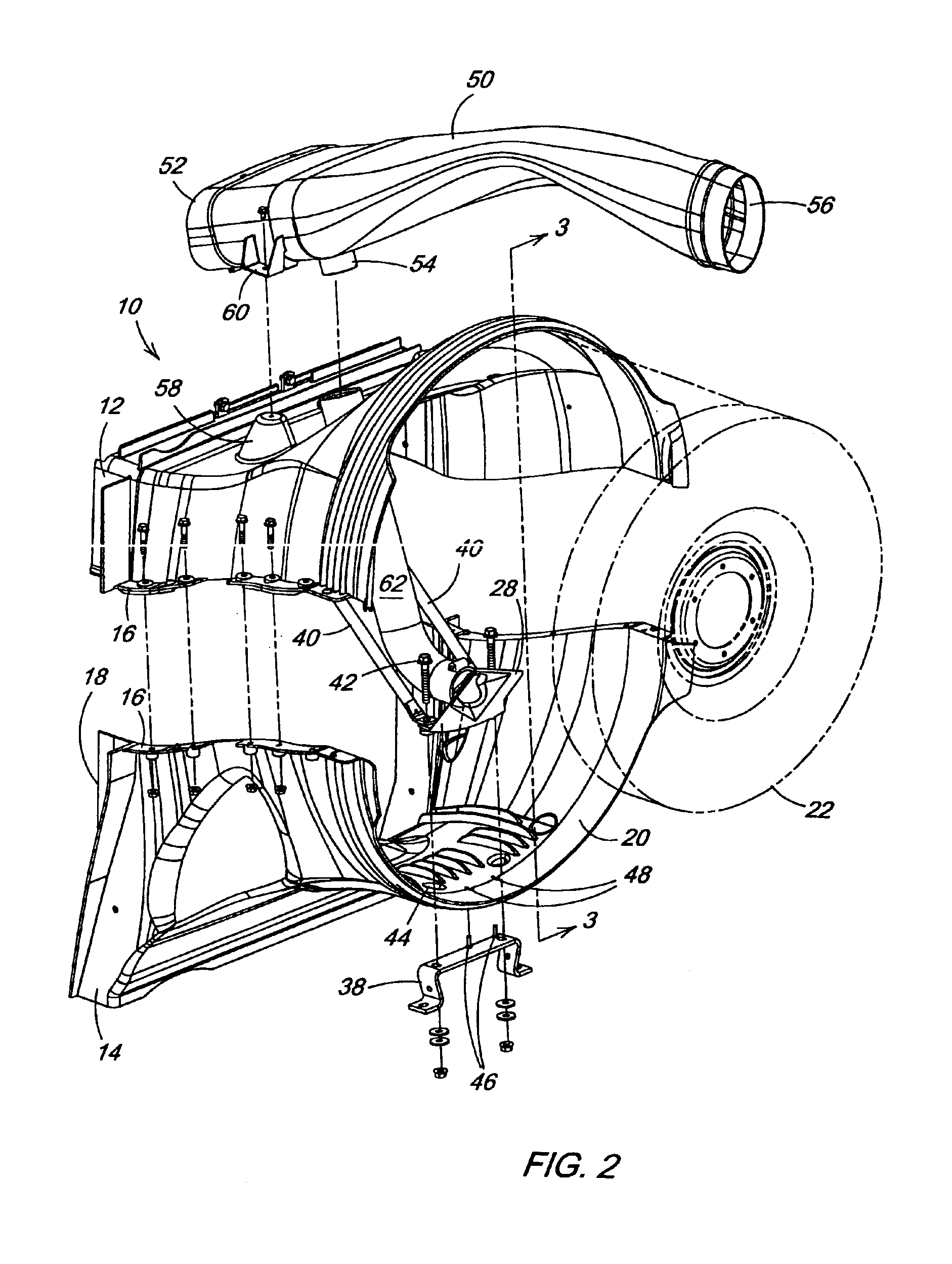
[0019]With reference now to the drawings and particularly FIGS. 1-3, it can be seen that a fan shroud having an internal aspirator according to the invention is designated generally by the numeral 10. As shown the fan shroud 10 is comprised of an upper section 12 and a lower section 14 and is preferably formed of a thermoplastic or thermoset material in an appropriate conventional molding process. The upper section 12 and the lower section 14 are designed to mateably engage one another at mating flanges 16 so as to form an air passage between a fan and a cooling module of the vehicle. Accordingly, a first end 18 of the shroud 10 is adapted for disposal proximal to the cooling module (not shown) while a second end 20 is adapted for disposal proximal to the fan 22. Thus air is drawn through the cooling module by the fan 22. As is perhaps best shown in FIG. 6 the upper section of shroud 10 includes an aspirator portal 24 in an upper surface 26 thereof.

[0020]Referring now to FIGS. 4 and...


PUM

PropertyMeasurementUnit
vacuumaaaaaaaaaa
temperatureaaaaaaaaaa
structureaaaaaaaaaa

Abstract

A fan shroud is provided having upper and lower sections. The sections are designed to mateably engage one another at mating flanges so as to form an air passage between a fan and a cooling module of the vehicle. The upper section of shroud includes an aspirator portal in an upper surface thereof. An aspirator is provided having an air intake and an air outlet. The aspirator is supported in the lower section of the shroud proximal to the fan with the air outlet facing the fan. An engine intake air pre-cleaner unit having an air intake, an aspirator port, and an air exhaust is mounted to the shroud by aligning mounting tabs on the pre-cleaner with mounting bosses on the shroud so that the aspirator port is disposed in proximity to the aspirator portal in the upper section of shroud. One end of an aspirator hose is connected to the aspirator port of the pre-cleaner and passes through the aspirator portal. The other end of the aspirator hose is connected to the air intake of the aspirator. The aspirator hose passes generally through the middle of the shroud from the upper section to the lower section. The vacuum necessary for proper aspiration of the pre-cleaner is accomplished by air movement, induced by the fan, between the air intake of the pre-cleaner and the aspirator via the aspirator port and the aspirator hose. No additional hoses or fittings are required outside the shroud to provide aspiration to the pre-cleaner so that considerable space is conserved under the vehicle hood.

Description

FIELD OF THE INVENTION[0001]The present invention relates generally to air intake systems for internal combustion engines. More particularly, the present invention relates to such systems which employ a pre-cleaner. Specifically, the present invention relates to aspirators for supplying a vacuum to such pre-cleaners.BACKGROUND OF THE INVENTION[0002]Engine air intake systems for work vehicles frequently include a pre-cleaner to remove dirt particles from the intake air prior to the air filter. Many pre-cleaners require a vacuum to pull or “scavenge” dirt particles from the fresh air ingested into the air intake system. Exhaust system aspirators have been used to supply the required vacuum. An exhaust system aspirator, however, creates a restriction in the engine exhaust, raises noise levels and raises the cost of the muffler and / or exhaust pipe. Also, a check valve is needed to prevent back flow of high temperature gases into the pre-cleaner and high temperature hoses must be used.[0...

Claims


Application Information

Patent Timeline
Patent Type & Authority Patents(United States)
IPC IPC(8): F01P5/06F01P5/02F02M35/02F02M35/022F02M35/06F02M35/08
CPCF01P5/06F02M35/022F02M35/08F02M35/06Y10S55/28
Inventor WIKNER, AARON DAVID
Owner DEERE & CO
Features
  • R&D
  • Intellectual Property
  • Life Sciences
  • Materials
  • Tech Scout
  • Unparalleled Data Quality
  • Higher Quality Content
  • 60% Fewer Hallucinations
Learn More