Vehicle regenerative braking apparatus

a regenerative braking and vehicle technology, applied in the direction of braking systems, battery/fuel cell control arrangements, electric generator control, etc., can solve the problems of affecting the smoothness of driving as perceived and felt by the driver, affecting the smoothness of driving, and exceeding the maximum charge amount of the battery, so as to prevent adverse effects on the battery and the effect of simple structur

Active Publication Date: 2005-06-21
DENSO CORP
View PDF11 Cites 44 Cited by
  • Summary
  • Abstract
  • Description
  • Claims
  • Application Information

AI Technical Summary

Benefits of technology

[0012]The present invention was devised to solve the above-mentioned problems, and it is therefore an object to provide a vehicle ...

Problems solved by technology

Therefore, the amount of power that can be accepted by the battery (maximum charge amount) is exceeded, and there is the possibility of detrimental effects to the battery.
However, if regenerative power is suddenly reduced then vehicle braking force (electrical braking force+frictional braking force) is lost and degrades the smoothness of driving as perceived and felt by the driver.
Even when compensation of the lost portion of electrical braking force by an increase in the frictional braking force of the hydraulic brake mechanism is attempted, it is difficult to make the speed of increase of frictional braking force from the hydraulic brake system match the dramatic speed of loss of regenerative power (several milliseconds).
However, when excess power is large it is very difficult to completely consume with this ge...

Method used


Image

  • Vehicle regenerative braking apparatus
  • Vehicle regenerative braking apparatus
  • Vehicle regenerative braking apparatus

Examples


Embodiment Construction

[0033]The following description of the preferred embodiments is merely exemplary in nature and is in no way intended to limit the invention, its application, or uses.

[0034]With reference to the drawings, preferred embodiments of a vehicle regenerative braking apparatus in accordance with the present invention will be described hereinafter.

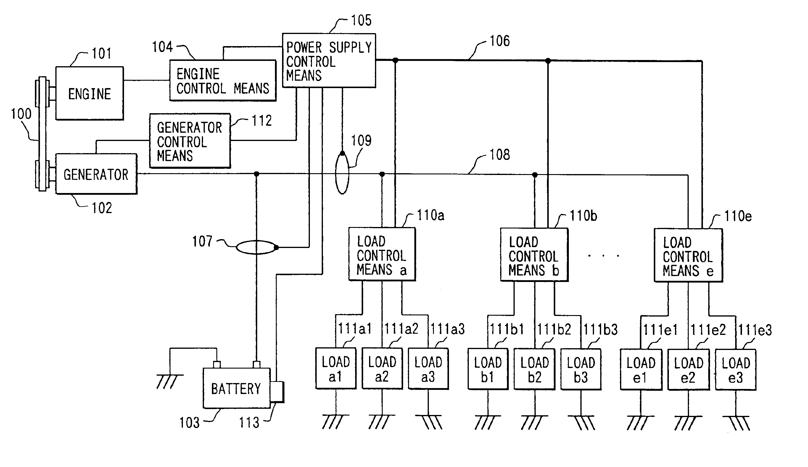
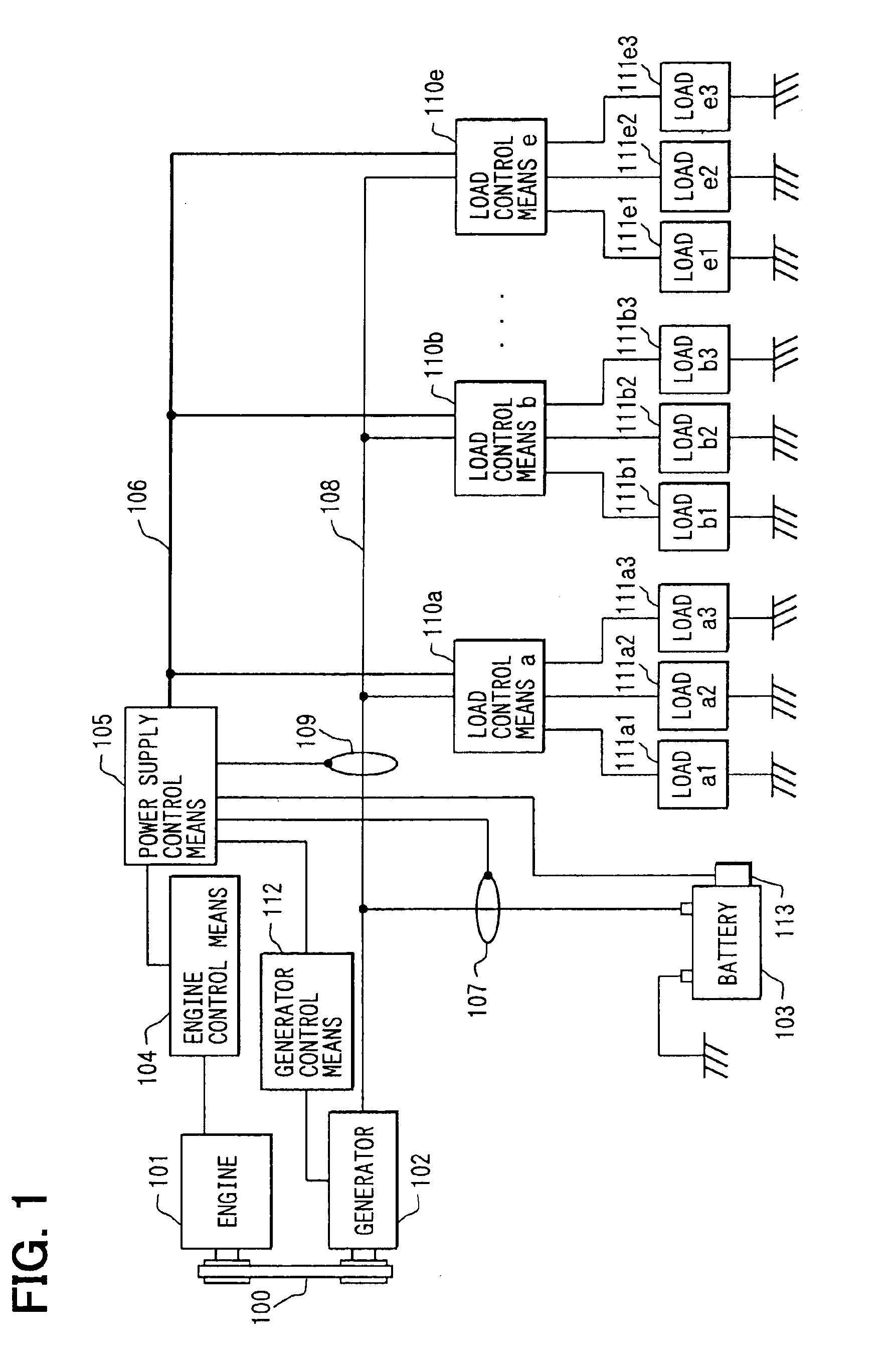
[0035]FIG. 1 is a block diagram showing an electrical system of a vehicle having a vehicle electrical load driving control apparatus according to one embodiment of the present invention.

[0036]Referring to FIG. 1, an engine 101 is linked to a generator 102 by a belt 100. The generator 102 is connected to a battery 103 and to load control means 110a to 110e via power supply line 108. The load control means 110a executes power supply control of loads 111a1 to 111a3, the load control means 110b executes power supply control of loads 111b1 to 111b3, and so forth in the same manner, and the load control means 110e executes power supply control of loads 1...


PUM


Abstract

A vehicle regenerative braking apparatus of simple structure is provided, which prevents adverse effects on a battery while handling excess power appropriately. In a vehicle regenerative braking, when excess power which exceeds a preferable charge amount of a battery has been generated as a result of regeneration, the excess power is consumed by increased power consumption of a plurality of electrical loads selected from among several electrical loads.

Description

CROSS REFERENCE TO RELATED APPLICATIONS[0001]This application is based upon, claims the benefit of priority of, and incorporates by reference Japanese Patent Application No. 2003-44205 filed Feb. 21, 2003.BACKGROUND OF THE INVENTION[0002]1. Field of the Invention[0003]The present invention relates to a vehicle regenerative braking apparatus.[0004]2. Description of the Related Art[0005]In recent years, a method for reclaiming or regenerating the deceleration energy of a vehicle by means of an electric machine has come into the stage of practical application with the goal of improving vehicle fuel efficiency. It is normal with vehicle regeneration methods to generate a braking force equivalent to the regenerative power (also called electrical braking force), and to make up the remaining required braking force with frictional force of the mechanical brake.[0006]However, during regeneration, if operation of a large power-consuming load (e.g., a PTC heater) is stopped during regeneration...

Claims


Application Information

Patent Timeline
IPC IPC(8): B60L7/26B60L7/00B60K25/00B60R16/02B60R16/033B60R16/04B60T8/17H02P9/04
CPCB60L7/26B60L2260/54B60L1/00B60L7/18B60L58/15Y02T10/70F16D61/00B60T1/10
Inventor OBAYASHI, KAZUYOSHITANI, KEISUKE
Owner DENSO CORP
Why Eureka
Try Eureka