Blower housing for furnace blower assembly

a furnace blower and assembly technology, applied in the direction of machines/engines, stators, liquid fuel engines, etc., can solve the problems of increasing parts inventory, difficult and laborious assembly, and parts that are somewhat difficult to manufacture, so as to reduce tooling, manufacturing and inventory costs

Inactive Publication Date: 2005-06-21
REGAL BELOIT AMERICA
View PDF9 Cites 13 Cited by
  • Summary
  • Abstract
  • Description
  • Claims
  • Application Information

AI Technical Summary

Benefits of technology

[0010]The present invention provides a blower housing for a furnace blower assembly of the type including a blower motor coupled to an impeller for use in expelling exhaust gases from a furnace. The blower housing generally includes an inlet, an impeller cavity, and an extension portion extending from the impeller cavity, the extension portion terminating in a circular outlet to which a round flue pipe may be attached. The blower housing is formed by three housing members joined to one another, wherein the housing members may be formed from metal using conventional stamping, drawing, and forming processes, for example. To form a variety of different types of blower housings having different outlet offset distances, only the dimensions of cooperating portions of two of the housing members need be varied, with one of the housing members used in common among the different types of blower housings. In this manner, a number of different types of blower housings may be made for furnaces of different designs while reducing tooling, manufacturing, and inventory costs.
[0012]Advantageously, the dimensions of the extension walls of the second and third housing members may be modified by a simple retooling of a portion of each of the second and third housing members. Varying the dimensions of the extension walls of the second and third housing members allows for the production of blower housings having a varying degree of offset distance between the planar wall of the second housing member which is attached to the furnace and the edge of the blower housing outlet. The shape of the first housing member need not be varied; rather, the first housing member is a component which is used in common between any number of different types of blower housings. In this manner, different blower housings may be produced in an economically efficient manner.

Problems solved by technology

However, blower housings which include a large number of components have the disadvantage of requiring an increased parts inventory, and also may be somewhat difficult and labor-intensive to assemble.
Although this type of construction results in a blower housing which is easy to assemble, the shapes of the two blower housing components requires complicated drawing operations to form the components, making the components somewhat difficult to manufacture and leading to increased tooling costs.
Thus, a blower housing which is designed for a particular furnace might not meet the specifications of other furnaces.

Method used


Image

  • Blower housing for furnace blower assembly
  • Blower housing for furnace blower assembly
  • Blower housing for furnace blower assembly

Examples


Embodiment Construction

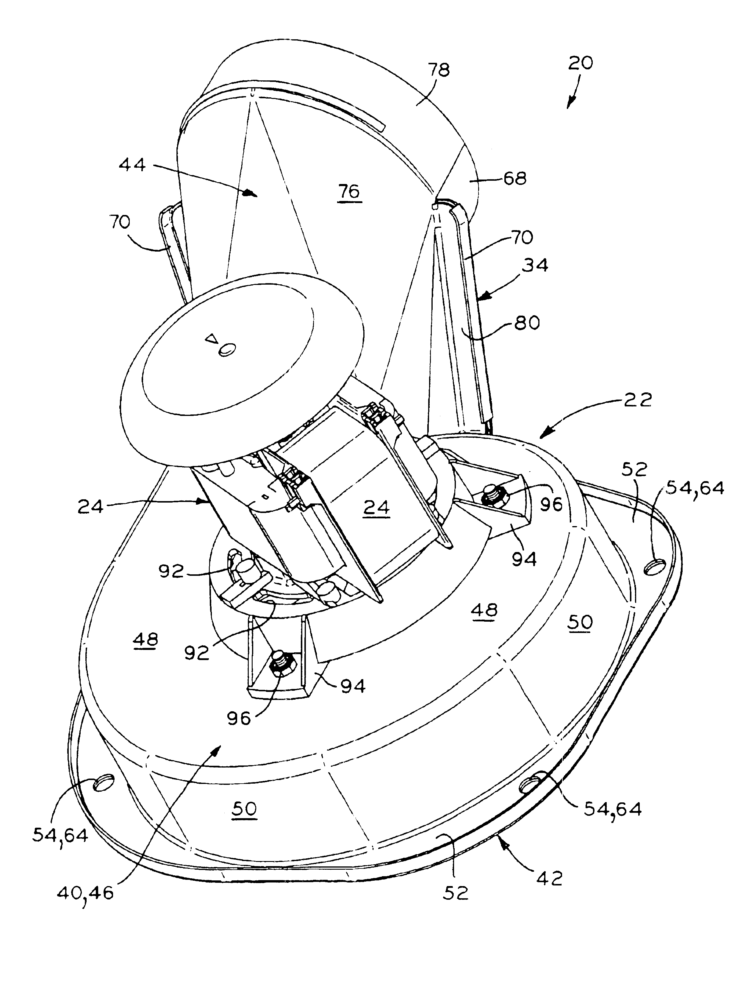
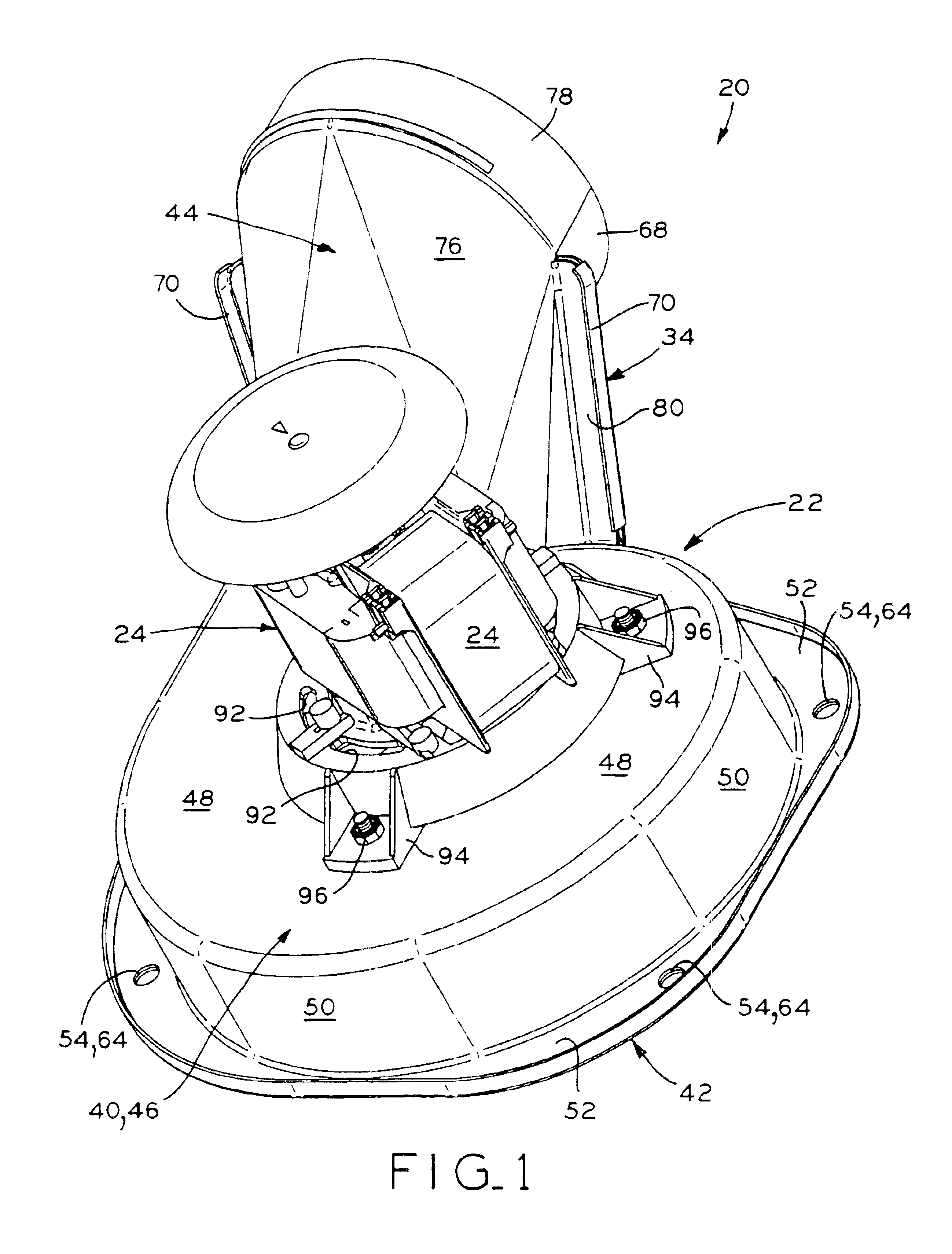
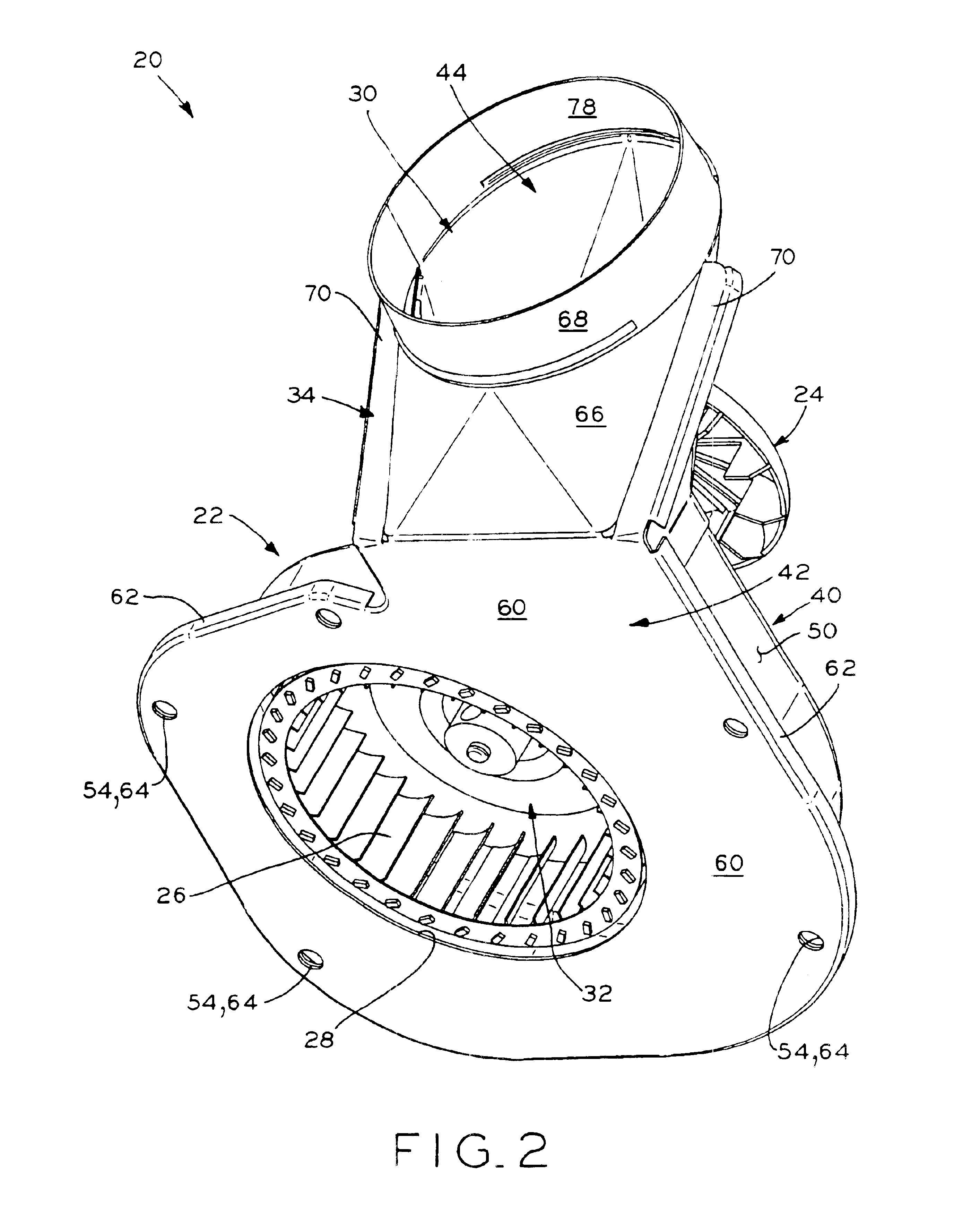
[0028]Referring to FIGS. 1-5, blower assembly 20 is shown, which includes a blower housing 22 in accordance with a first embodiment of the present invention. Except as described below, blower assembly 20 includes many features which are similar to the blower assembly disclosed in U.S. Pat. No. 6,468,034, assigned to the assignee of the present invention, the disclosure of which is expressly incorporated herein by reference. Blower assembly 20 generally includes blower housing 22, motor 24 mounted to blower housing 22, and impeller 26 disposed within blower housing 22. Impeller 26 is rotatably driven by motor 24 to draw air from within a furnace (not shown) to which blower assembly 20 is attached through inlet 28 of blower housing 22 and out through outlet 30 of blower housing 22.

[0029]Blower housing 22 generally includes inlet 28, impeller cavity 32 in which impeller 26 is disposed, extension or transition portion 34 extending from impeller cavity 32, and outlet 30 at the end of ext...


PUM

PropertyMeasurementUnit
shapeaaaaaaaaaa
dimensionsaaaaaaaaaa
degree of offset distanceaaaaaaaaaa

Abstract

A blower housing for a furnace blower assembly of the type including a blower motor coupled to an impeller for use in expelling exhaust gases from a furnace. The blower housing generally includes an inlet, an impeller cavity, and an extension portion extending from the impeller cavity, the extension portion terminating in a circular outlet to which a round flue pipe may be attached. The blower housing is formed by three housing members joined to one another, wherein the housing members may be formed from metal using conventional stamping, drawing, and forming processes, for example. To form a variety of different types of blower housings having different outlet offset distances, only the dimensions of cooperating portions of two of the housing members need be varied, with one of the housing members used in common among the different types of blower housings. In this manner, a number of different types of blower housings may be made for furnaces of different designs while reducing tooling, manufacturing, and inventory costs.

Description

BACKGROUND OF THE INVENTION[0001]1. Field of the Invention[0002]The present invention relates to blower housings for furnace blower assemblies, the blower housings including an outlet for the attachment of a flue pipe.[0003]2. Description of the Related Art[0004]Blower assemblies are used in modern furnaces to increase the fuel efficiency of the furnace burner by inducing a draft through the furnace to draw heated air and products of combustion through a heat exchanger within the furnace and exhaust same through an exhaust pipe. Typically, the blower assembly includes a blower housing mounted to the furnace, the blower housing defining an impeller cavity therein. The blower housing also includes a mounting surface for mounting a motor to the blower assembly. The motor includes an output shaft to which an impeller is affixed, the impeller disposed within the impeller cavity. In operation, the motor rotatably drives the impeller to draw heated air and exhaust gases from the furnace in...

Claims


Application Information

Patent Timeline
Patent Type & Authority Patents(United States)
IPC IPC(8): F03B11/00F04D29/42F04D29/62
CPCF04D29/4226F04D29/626Y10T29/49243
Inventor LYONS, LESLIE A.STEPHENS, HARRY L.
Owner REGAL BELOIT AMERICA
Why Eureka
Try Eureka