Storage peripheral having a robust serial advanced technology attachment (SATA) PCB connector

a technology of sata cable and peripheral, applied in the direction of recording information storage, coupling device connection, instruments, etc., can solve the problems of insufficient protection of sata cable connectors, and prone to mechanical failure of blade connectors specified by sata standards

Inactive Publication Date: 2005-06-21
WESTERN DIGITAL TECH INC
View PDF25 Cites 164 Cited by
  • Summary
  • Abstract
  • Description
  • Claims
  • Application Information

AI Technical Summary

Benefits of technology

[0026]In a more detailed embodiment, the storage peripheral may include a second blade connector having a second electrical contact arrangement in accordance with the SATA standard. The second blade connector is also located inside of the cable connector receiving area of the housing. For example, in one embodiment, the first electrical contact arrangement may be configured for data signals in accordance with the SATA standard and the second electrical contact arrangement may be configured for power signals in accordance with the SATA standard.
[0027]In yet a more detailed embodiment, the housing may include a substantially thickened strengthening wall disposed between the cable connector receiving area and the guide arm receiving cavity. The guide arm receiving cavity may include a conductive surface. For example, the conductive surface may include a grounding tab. In another embodiment, the housing and the guide arm receiving cavity may be made from a conductive plastic material. Further, the guide arm receiving cavity may be approximately rectangularly shaped. Additionally, the SATA standard may be a Serial

Problems solved by technology

Unfortunately, the blade connectors specified by the SATA standard are prone to mechanical failure when utilizing presently manufactured SATA compliant cable connectors and PCB connectors.
This is because mating SATA cable connectors are not suitably constrained by the housing

Method used


Image

  • Storage peripheral having a robust serial advanced technology attachment (SATA) PCB connector
  • Storage peripheral having a robust serial advanced technology attachment (SATA) PCB connector
  • Storage peripheral having a robust serial advanced technology attachment (SATA) PCB connector

Examples


Embodiment Construction

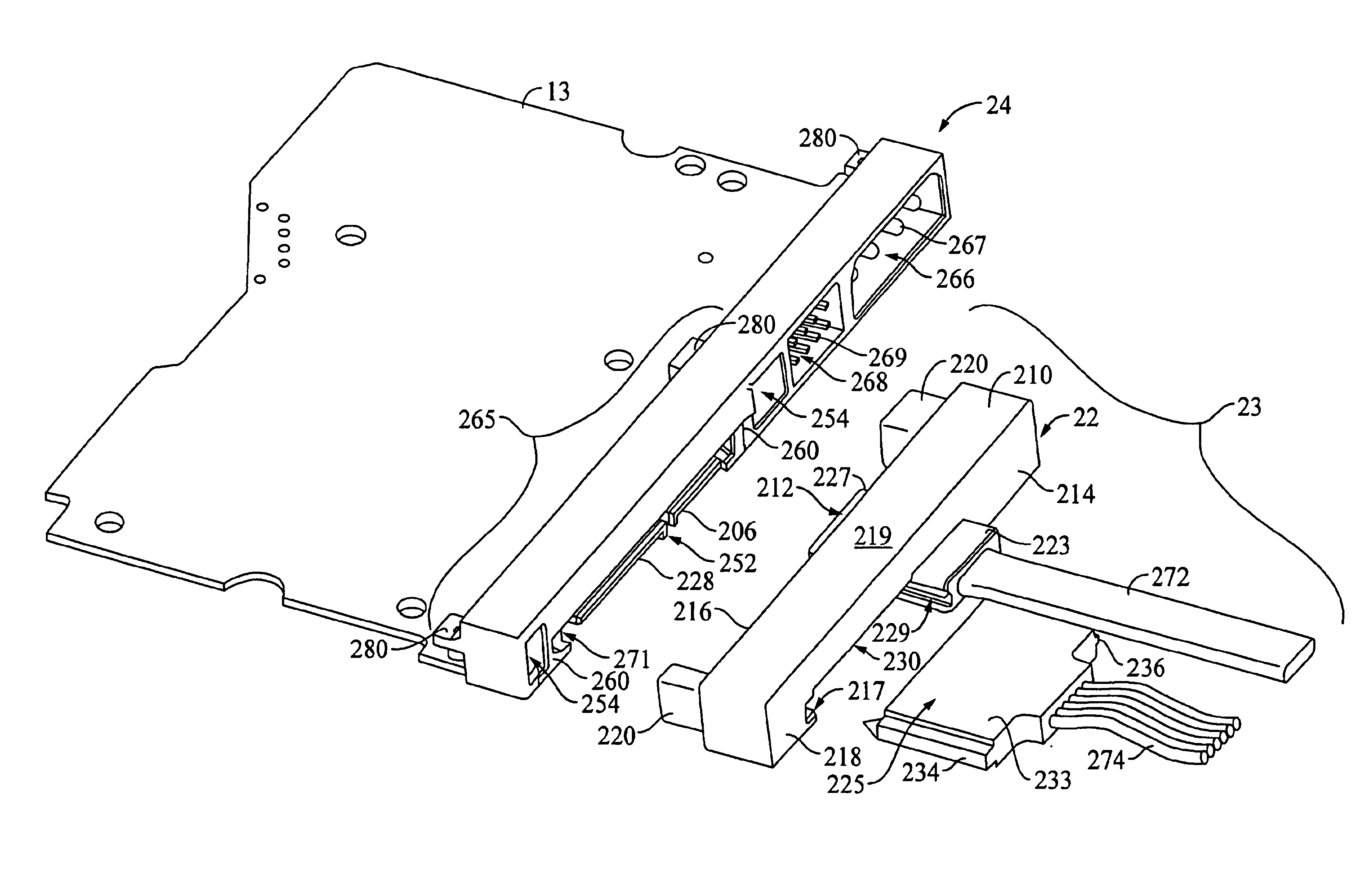
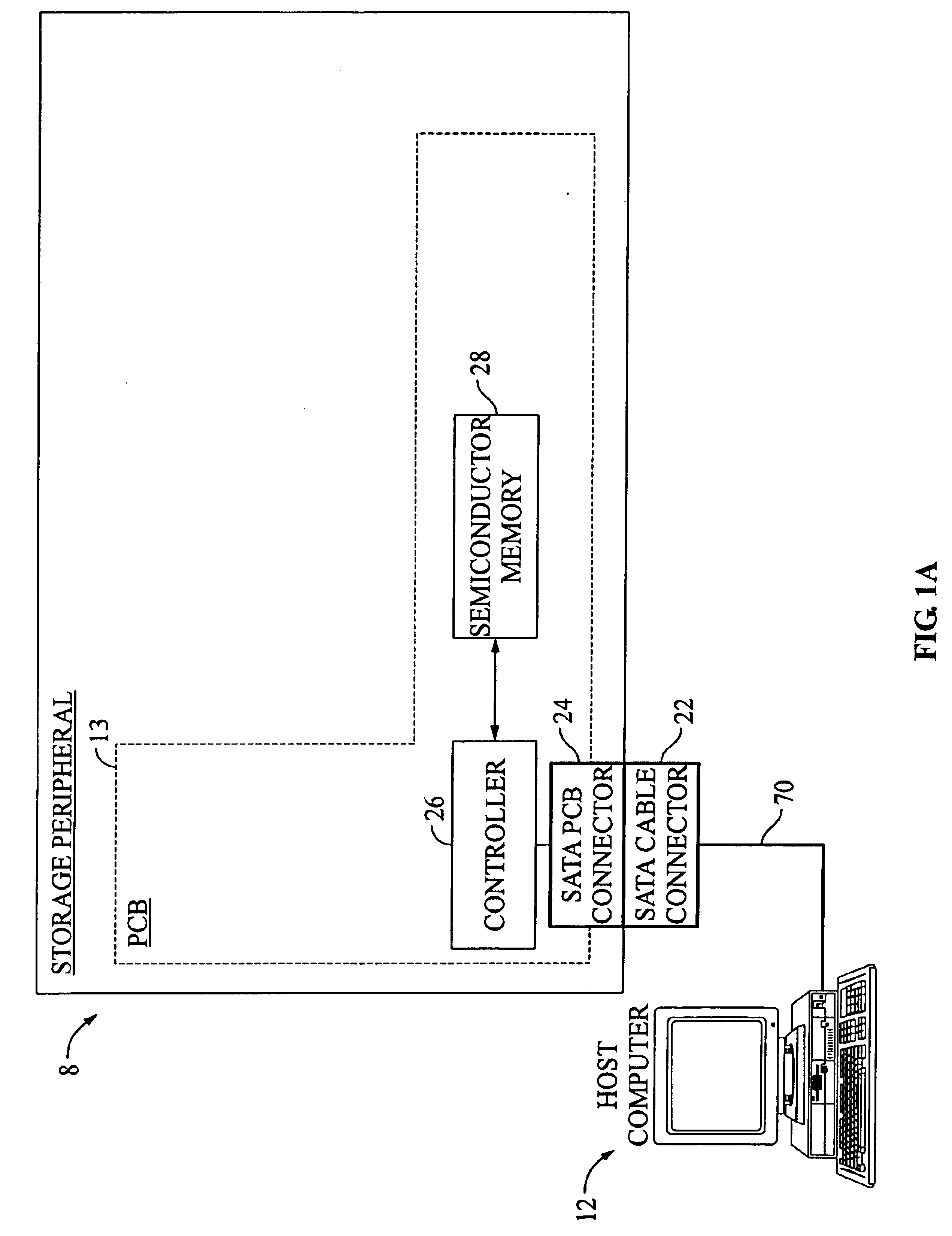
[0052]With reference to FIG. 1A, FIG. 1A shows a block diagram of a system including a host computer 12 connected to a storage peripheral 8, in which embodiments of the invention may be practiced. The storage peripheral 8 comprises a controller 26 having a Serial ATA (SATA) interface (not shown) connected to a SATA PCB connector 24. The storage peripheral 8 further includes a semiconductor memory 28 for data storage and retrieval. The controller 26, semiconductor memory 28, and SATA PCB connector 24 are preferably mounted on a printed circuit board (PCB) 13. The storage peripheral 8 is connectable to a host computer 12 for receiving commands and data over a SATA cable 70 having a SATA cable connector 22.

[0053]In one embodiment, storage peripheral 8 may emulate a disk drive while communicating with the host computer 12 using a SATA protocol. Semiconductor memory 28 may be a Flash memory system for providing non-volatile storage. In another embodiment, semiconductor memory 28 may be a...


PUM


Abstract

A storage peripheral, such as disk drive, having a robust PCB connector configured in accordance with a SATA standard. The disk drive has a disk, a disk controller system, and a PCB for mounting the disk controller system, and a housing attached to the PCB. A first electrical contact arrangement in accordance with a SATA standard is connected to the PCB and is supported by a first blade connector. Both the first blade connector and the first electrical contact arrangement are enclosed by the housing. The housing further defines a cable connector receiving area around the first blade connector for the receipt of a cable connector. A pair of laterally-opposed guide arm receiving cavities are integrally formed with the housing and are disposed outside of the cable connector receiving area. The guide arm receiving cavities are adapted for the receipt of guide arms from a mating cable connector.

Description

BACKGROUND OF THE INVENTION[0001]1. Field of the Invention[0002]The present invention relates to connectors. More particularly, the present invention relates to a storage peripheral having a robust printed circuit board (PCB) connector configured in accordance with a Serial Advanced Technology Attachment (SATA) standard.[0003]2. Description of the Prior Art and Related Information[0004]Today, computers are routinely used both at work and in the home. Computers advantageously enable file sharing, the creation of electronic documents, the use of application specific software, and electronic commerce through the Internet and other computer networks. Typically, each computer has a storage peripheral. For example, the most common type of storage peripheral is a rotating media storage device (RMSD), such as a disk drive (e.g. a hard disk drive). However, other types of storage peripherals such as solid-state disk drive emulators utilizing flash memory are becoming increasingly common.[000...

Claims


Application Information

Patent Timeline
IPC IPC(8): G11B33/12H01R12/00H01R12/16H01R13/518H01R13/516
CPCH01R13/518G11B33/122H01R12/7005H01R12/79H01R12/724
Inventor GARRETT, WILLIAM W.GOLDSTONE, MARC B.SINGH, DALWINDERMORGAN, COLIN W.BASKOVICH, MARK A.
Owner WESTERN DIGITAL TECH INC
Why Eureka
Try Eureka