Disk controller methods and apparatus with improved striping, redundancy operations and interfaces

a disk array controller and striping technology, applied in the field of raid disk array controllers, can solve the problems of limited data transfer rate, low probability of data loss, limited hard disk performance, etc., and achieve the effect of reducing buffer requirements, improving performance, and reducing hardware complexity

Active Publication Date: 2005-10-06
NVIDIA CORP
View PDF8 Cites 105 Cited by
  • Summary
  • Abstract
  • Description
  • Claims
  • Application Information

AI Technical Summary

Benefits of technology

[0036] A RAID disk drive controller implements disk storage operations, including striping and redundancy operations with multiple disk drives connected via respective source synchronous ports, e.g. SATA ports. Configurable data path switch logic provides dynamic configuration of two or more attached drives into one or more arrays. Data transfers are synchronized locally by leveraging the SATA por...

Problems solved by technology

As an electromechanical device, the hard disk performance is limited by the physical characteristics of the drive consisting primarily of seek times and rotational delays.
Once the mechanical portion of a read or write access has been performed, the data transfer rate is limited by characteristics of the media, the head, and the R/W electronics.
If a failed drive is immediately replaced and the copy rebuilt, the probability of data loss drops down to the probability of two drive failures within the time required to replace a failed drive and to rebuild the copy.
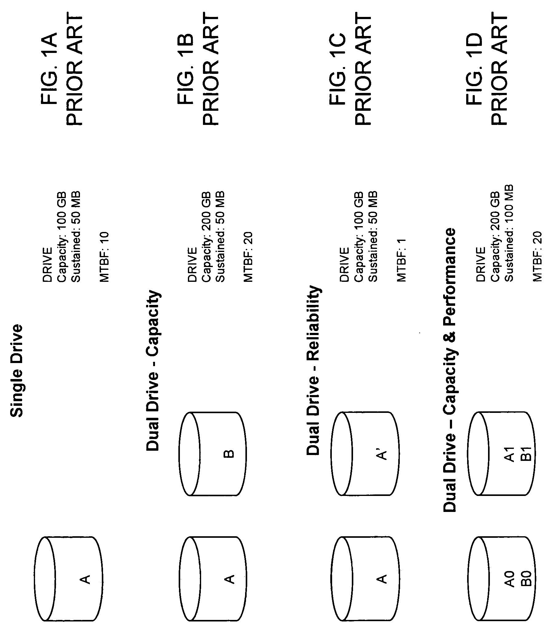
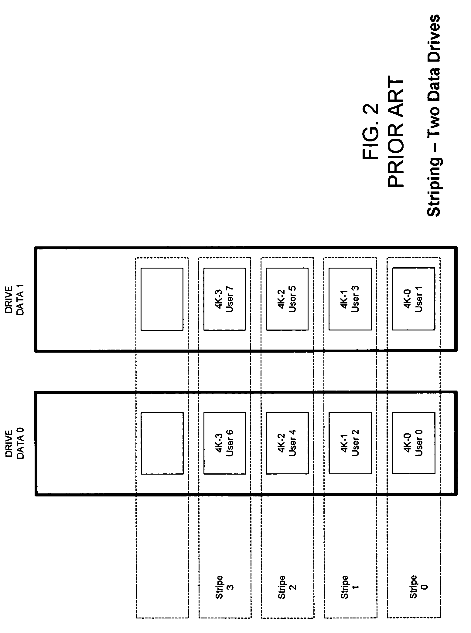
First, a high speed streaming application may require a higher sustained bandwidth than a single drive can deliver.
And second, the access time for a given drive, determined primarily by seek and rotational delays, limits the number of IO operations that can be performed per second (“IOPS”).
The simple addition of a second drive to a system will immediately double the capacity, but there may not be a performance improvement.
Should the bulk of the accesses be to one of the drives or the other, the performance will be limited by performance of the more popular drive.
The increased reliability results in a 100% increase in the cost of storage, i.e. one mirror drive...

Method used


Image

  • Disk controller methods and apparatus with improved striping, redundancy operations and interfaces
  • Disk controller methods and apparatus with improved striping, redundancy operations and interfaces
  • Disk controller methods and apparatus with improved striping, redundancy operations and interfaces

Examples


Embodiment Construction

I. RAID Controllers and the UDMA Disk Drive Interface.

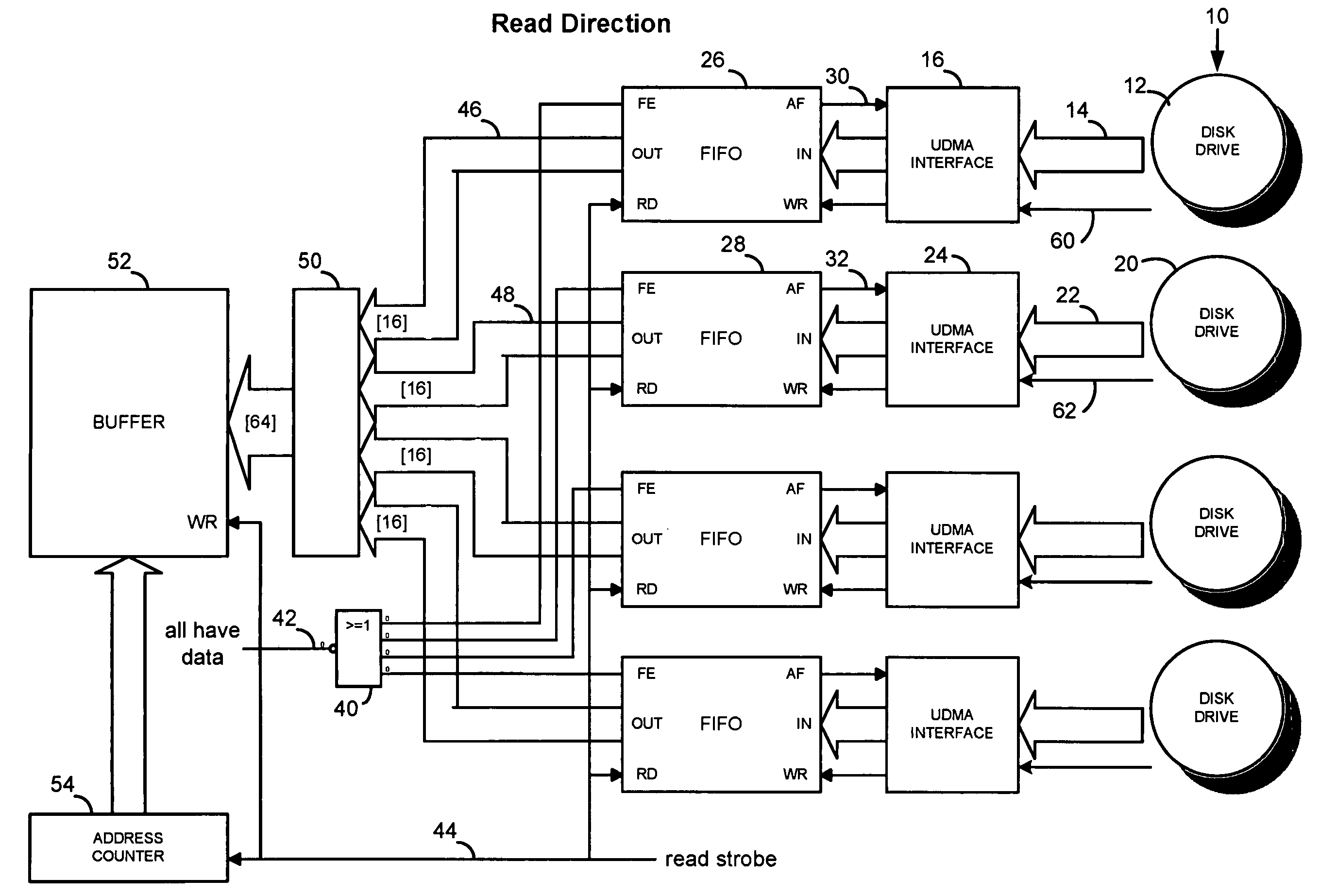
[0087] It is useful to create synchronous data transfers in a disk controller where the actual data transfers to and from the disk drives are asynchronous. That is, for some interfaces and protocols, the disk transfer operations are paced not by the disk controller, but by the individual drive electronics, and each drive completes its part of a given operation, for example a read or write of striped data, at a different time. The availability of synchronous data transfers enables “on the fly” generation of redundancy information (in the disk write direction) and “on the fly” regeneration of missing data in the read direction (in the event of a disk failure).

[0088] This can be done by placing an elastic buffer, i.e. a FIFO, into the data path of each of the drives and the controller. This strategy is illustrated with the case of a UDMA interface, although it can be used in any application where a data strobe originates at the dat...


PUM


Abstract

A RAID disk drive controller (FIG. 33) implements disk storage operations, including striping and redundancy operations with multiple disk drives connected via respective SATA ports (520). Configurable data path switch logic (460) provides dynamic configuration of two or more attached drives into one or more arrays. Data transfers are synchronized locally by leveraging the SATA port transport layer FIFO (530). Synchronous transfers allow on-the-fly redundancy (XOR) operations (FIG. 36) for improved performance and reduced hardware complexity. XOR accumulator hardware (FIG. 42-FIG. 43) reduces buffer requirements for multiple DMA channels otherwise required for synchronization, and various narrow and wide striping modes are supported.

Description

PRIORITY CLAIM AND RELATED CASES [0001] This application claims priority from U.S. Provisional Application No. 60 / 553,594 filed Mar. 12, 2004. Said provisional application is incorporated herein in its entirety by this reference. This application also is a CIP of U.S. application Ser. No. 10 / 822,115 filed Apr. 8, 2004 and incorporated herein in its entirety by this reference. This application also is a CIP of U.S. application Ser. No. 10 / 829,918 filed Apr. 21, 2004 and incorporated herein in its entirety by this reference.TECHNICAL FIELD [0002] This invention is in the field of digital data storage systems and, more specifically, pertains to improvements in RAID disk array controllers. BACKGROUND OF THE INVENTION [0003] The hard disk remains the primary mass storage device for small to mid-sized computers. As an electromechanical device, the hard disk performance is limited by the physical characteristics of the drive consisting primarily of seek times and rotational delays. Once th...

Claims


Application Information

Patent Timeline
IPC IPC(8): G06F11/00G06F11/10
CPCG06F3/0617G06F3/0656G06F3/0689G06F11/1076G06F2211/1054
Inventor STOLOWITZ, MICHAEL C.
Owner NVIDIA CORP
Why Eureka
Try Eureka