
Trim apparatus for marine outdrive with steering capability

a trim apparatus and outdrive technology, applied in marine propulsion, rotary propellers, vessel construction, etc., can solve the problems of hydraulic steering and trim cylinders being exposed to the marine environment, large undesirable force applied along the axis of the drive, and undesirable bending and torsional loads, etc., to facilitate the pivoting movement of the propeller end, reduce the exposure, and facilitate the effect of manufacturing and servi

Active Publication Date: 2005-06-21
ZF FRIEDRICHSHAFEN AG
View PDF8 Cites 18 Cited by
  • Summary
  • Abstract
  • Description
  • Claims
  • Application Information

AI Technical Summary

Benefits of technology

The present invention provides a marine outdrive steering and trim system that overcomes the shortcomings of prior art systems. The system includes a support linkage, steering actuators, and a steering yoke for pure force coupling for steering the outdrive. The actuators are compact and light weight with high mechanical efficiency, but without being subjected to undesirable torsional or bending loads. The system does not require a significant amount of interior space or area for accommodating the actuators. The support linkage connected with the steering actuators via a steering yoke facilitates steering of the marine outdrive by movement of the steering yoke connected with the support linkage. The system also minimizes exposure to the various hydraulic conduits and electrical wires of the marine outdrive to harsh marine conditions by accommodating them within the interior of the marine vessel. The system is relatively simple to manufacture, service, and isolates the cylinder of the support linkage from excess steering and bending loads. The method of steering the marine outdrive includes supporting a rotatable propeller at the propeller end of the marine outdrive, mounting the opposite end of the marine outdrive to a marine vessel, attaching a first end of a support linkage to a transom and attaching a second end of the support linkage adjacent the propeller end of the marine outdrive, supporting a steering yoke adjacent the first end of the support linkage, connecting a first end of each of first and second steering actuators with the steering yoke, and connecting a second end of each of the first and second steering actuators with the transom such that the first and second steering actuators are spaced apart from one another.

Problems solved by technology

In many applications, space limitations and the typical hull geometry allow only one steering linkage per outdrive to be used.
In these cases, a substantial portion of the hydraulic force generated by the steering linkage is not applied in the direction required for steering thereby resulting in a large undesirable force being applied along the axis of the drive.
These configurations also result in the hydraulic steering and trim cylinders being exposed to the marine environment and experience undesirable bending and torsional loads in addition to providing forces along the cylinder axis.
Designing to accommodate this forces would tend to result in a heavy apparatus for high performance marine outdrives.
However, dealing with the associated design loads results in a fairly heavy apparatus which requires significant interior space.

Method used


Image

  • Trim apparatus for marine outdrive with steering capability
  • Trim apparatus for marine outdrive with steering capability
  • Trim apparatus for marine outdrive with steering capability

Examples


first embodiment

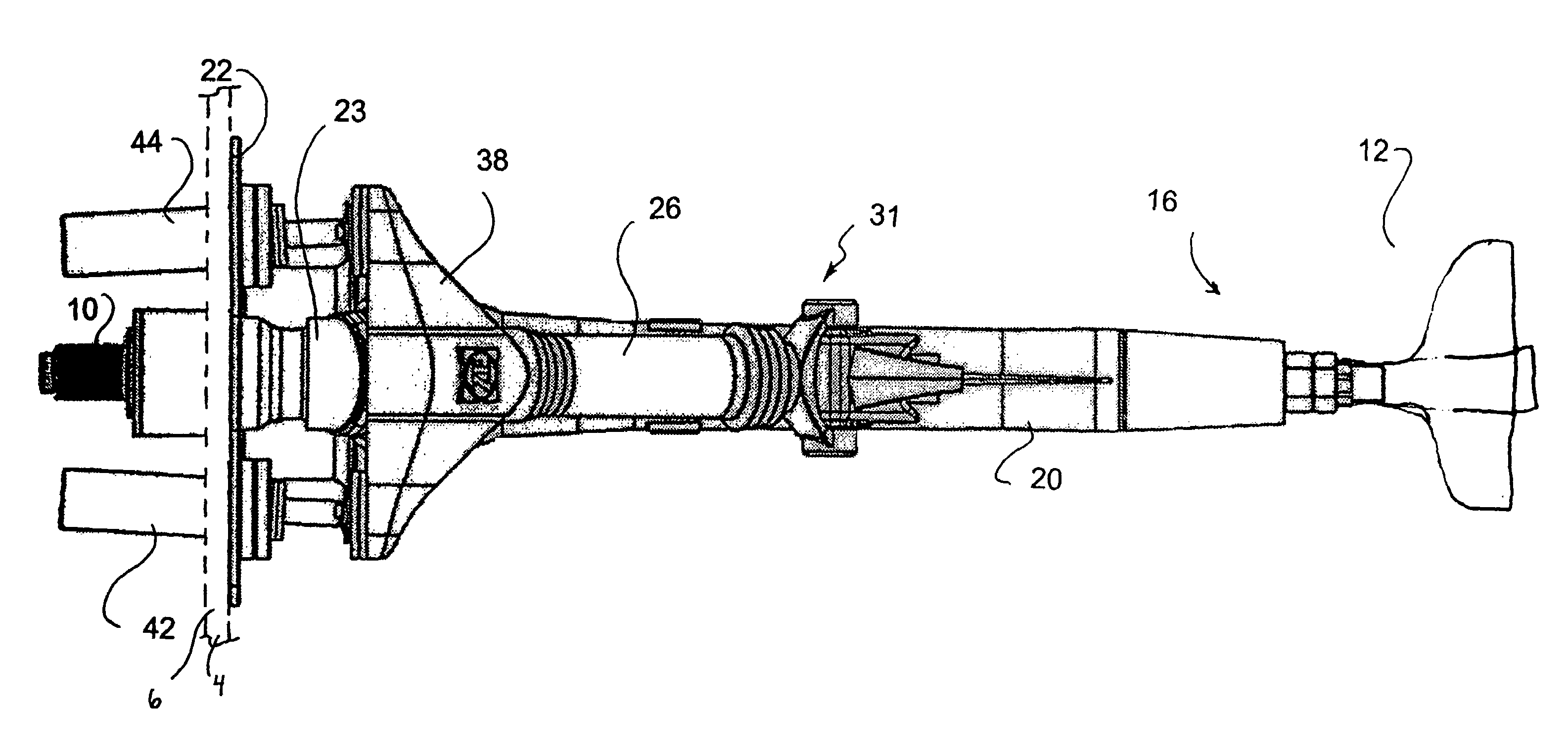
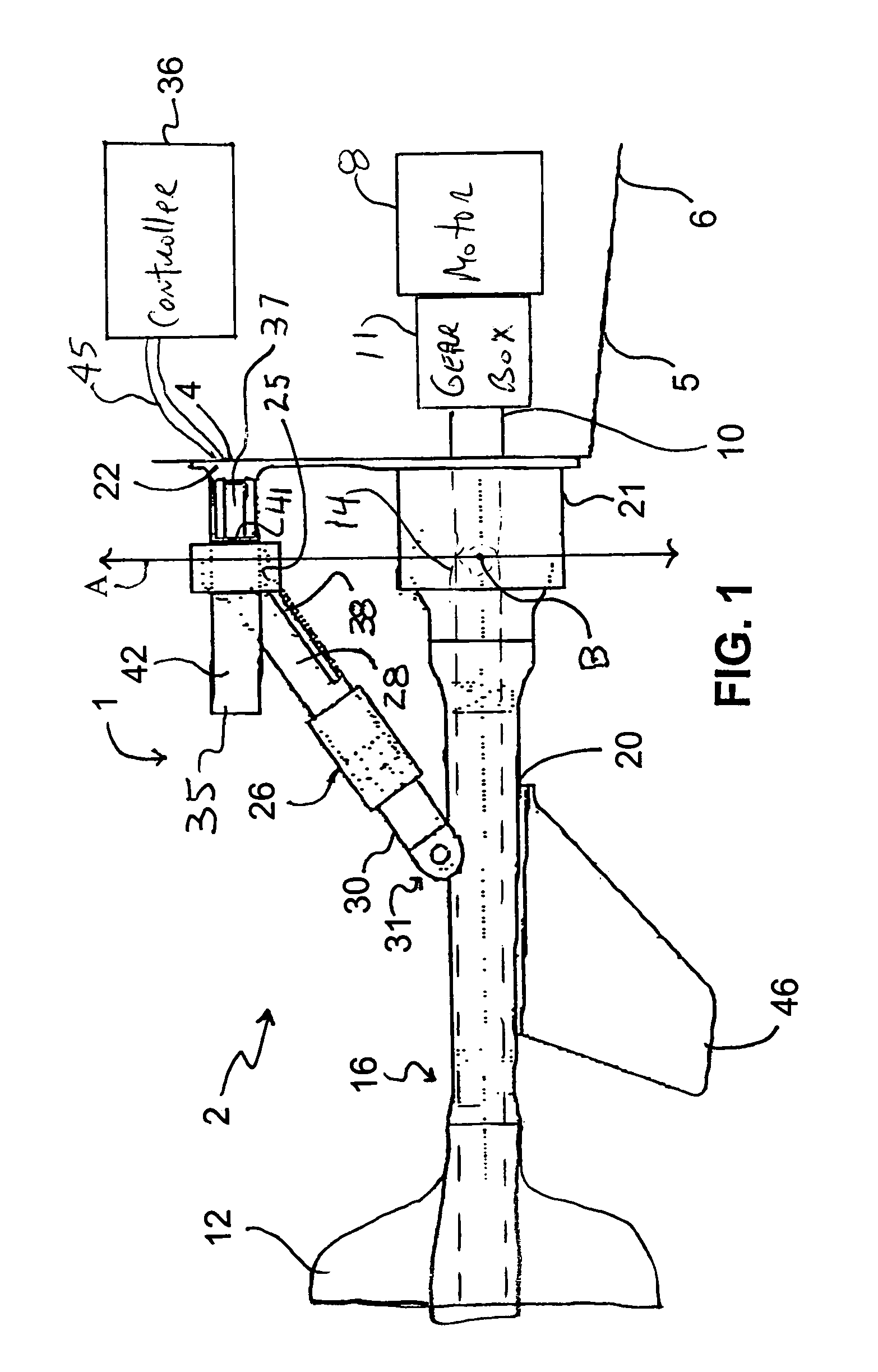
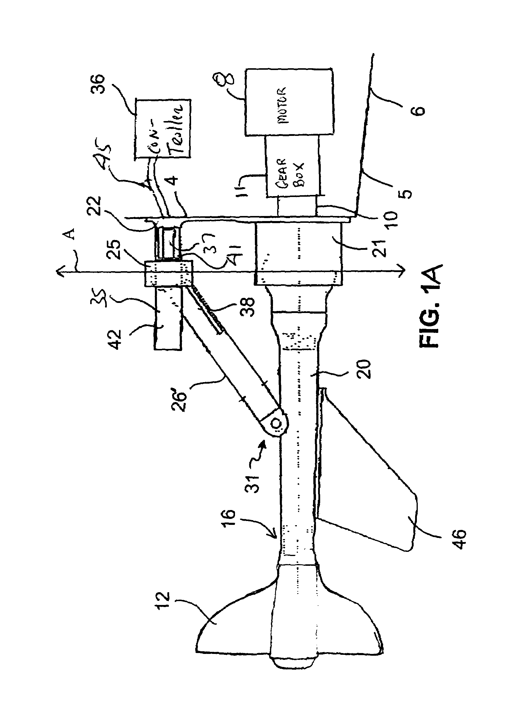
[0028]With reference now to FIGS. 1 and 2, the steering and trim marine outdrive system 1 will now be described. The marine outdrive 2 is mounted to transom 4 of a hull 5 of a marine vessel 6, such as a boat which is only partially shown in these Figures, in a conventional fashion with suitable fasteners and associated hardware (not shown in detail). An engine, drive or motor 8 is mounted within the marine vessel 6 and coupled, in a conventional manner, by an internal shaft to a gear box 11 and the drive shaft 10 for supplying rotational drive to the propeller 12 connected to a remote end of the marine outdrive 2. As is conventional in the art, a U-joint 14 (see FIG. 6) is located along the drive path, e.g., along the drive shaft 10, to permit vertical and / or horizontal movement of the remote propeller end 16 of the marine outdrive 2. In addition, the thrust generated by the propeller 12 of the marine outdrive 2, as the propeller 12 rotates in the water, is initially conveyed back a...

second embodiment

[0041]With reference now to FIGS. 3 through 9, the steering and trim marine outdrive will now be described. Like or similar elements in this embodiment with be given the same reference numerals.

[0042]According to the second embodiment, the orientation of the steering actuators 42, 44 are reversed. That is, the piston chambers for both of the steering actuators 42, 44 are accommodated generally inside the marine vessel 6 such that the transom 4 separates the piston heads and piston chambers (not shown in detail) of the steering actuators 42, 44 from a remainder of the steering actuators 42, 44. This embodiment represents the preferred orientation for the steering actuators 42, 44 since protection is provided for the steering hydraulic conduits and electrical wires 45 from the marine environment and assists with easier access to these components.

[0043]The transom plate 22 is secured to the outwardly facing surface of the transom 4 and this plate facilitates securing the steering actua...


PUM


Abstract

A marine outdrive (2) steering and trim system comprising a support linkage (26) which is either of fixed length (non-trimmable) or of an adjustable telescoping length (trimmable) and having a first end (28) pivotally mounted to the transom (4) and a second opposed end (30) attached to a propeller end (16) of the marine outdrive (2). A pair of steering actuators (42, 44) are connected between a steering yoke (38), secured to the support linkage (26), and a stationary pivot point on the transom (4) for providing a pure force couple to facilitating steering of the marine outdrive (2).

Description

FIELD OF INVENTION[0001]The present invention relates to improvements concerning a steering and trim apparatus for a marine outdrive system.BACKGROUND OF INVENTION[0002]U.S. Pat. No. 3,933,116 describes and shows a steering and trim apparatus for a marine device. According to this invention, a propeller shaft bearing box is horizontally pivoted in a gimbal ring, and the ring is vertically pivoted in the gimbal support frame. A tiller is secured on the gimbal ring vertical pivot shaft for horizontally swinging the propeller shaft to control steering. As shown in the drawings of that patent, the steering tiller is brought forward into the hull through an enlarged opening which must be sealed if the hull is submerged below this point. It is also evident in the general arrangement of this invention that the steering tiller is not suitable for counteracting large side forces typically generated by high performance marine outdrives.[0003]U.S. Pat. No. 4,544,362 and U.S. Pat. No. 4,645,463...

Claims


Application Information

Patent Timeline
Patent Type & Authority Patents(United States)
IPC IPC(8): B63H25/42B63H1/18B63H5/00B63H5/125B63H25/00B63H1/00
CPCB63H1/18B63H25/42B63H5/125
Inventor ROESSLER, EDMUND B.PLATZER, GREGORY P.SPARKS, RICHARD K.
Owner ZF FRIEDRICHSHAFEN AG
Learn More