Highly efficient shaft coupling

a shaft coupling, high-efficiency technology, applied in the direction of yielding couplings, linear bearings, bearings, etc., can solve the problems of reducing the efficiency of torque transmission, and not overcoming the boring friction load on the rolling member passage, so as to ensure the axial sliding ability, reduce the radial load on the bearing, and ensure the effect of axial sliding

Inactive Publication Date: 2005-06-21
AMBORN PETERT
View PDF17 Cites 6 Cited by
  • Summary
  • Abstract
  • Description
  • Claims
  • Application Information

AI Technical Summary

Benefits of technology

[0008]In view thereof, it is the object of the invention to propose an axially slidable shaft coupling that, on the one side, ensures the axial slidability of the coupling ...

Problems solved by technology

This is not only detrimental to the efficiency of the torque transmission from the driving to the driven shaft coupling member but also causes a non negligible mechanical boring friction load to be exerted on the rolling member passages mentioned.
The drawbacks described herein above with respect to the efficiency of the torqu...

Method used


Image

  • Highly efficient shaft coupling
  • Highly efficient shaft coupling
  • Highly efficient shaft coupling

Examples


Embodiment Construction

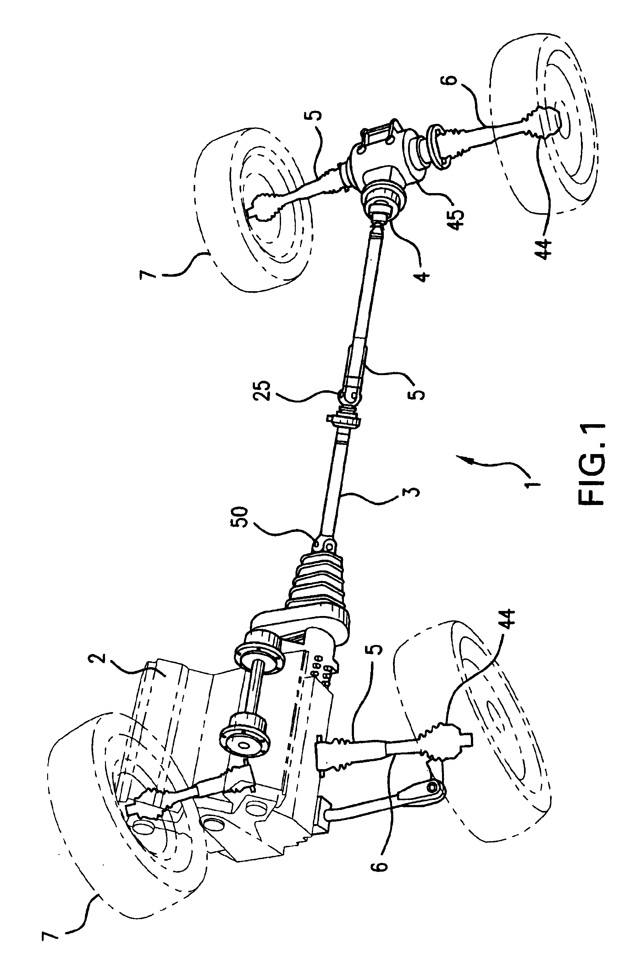
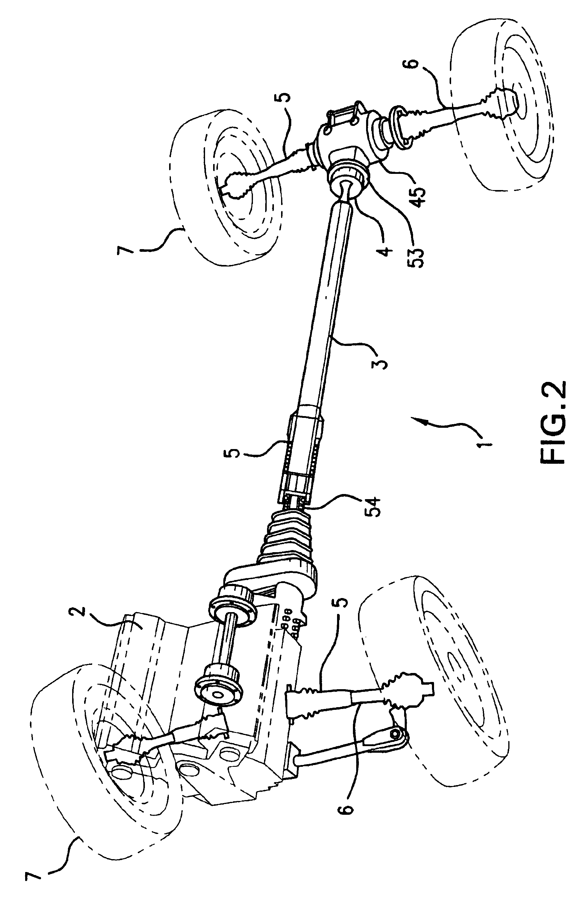
[0037]Accordingly, FIG. 1 shows a complete drive unit 1 of a four-wheel motor vehicle with a power unit 2 that produces and distributes a drive torque for drive wheels 7 of front and rear axles. A distributor gear, which is not shown in detail herein and which distributes the torque supplied by the engine to the drive shafts or side shafts 6 of the front wheels and, through a propeller shaft 3, to the drive or side shafts 6 of the rear wheels, is provided for this purpose.

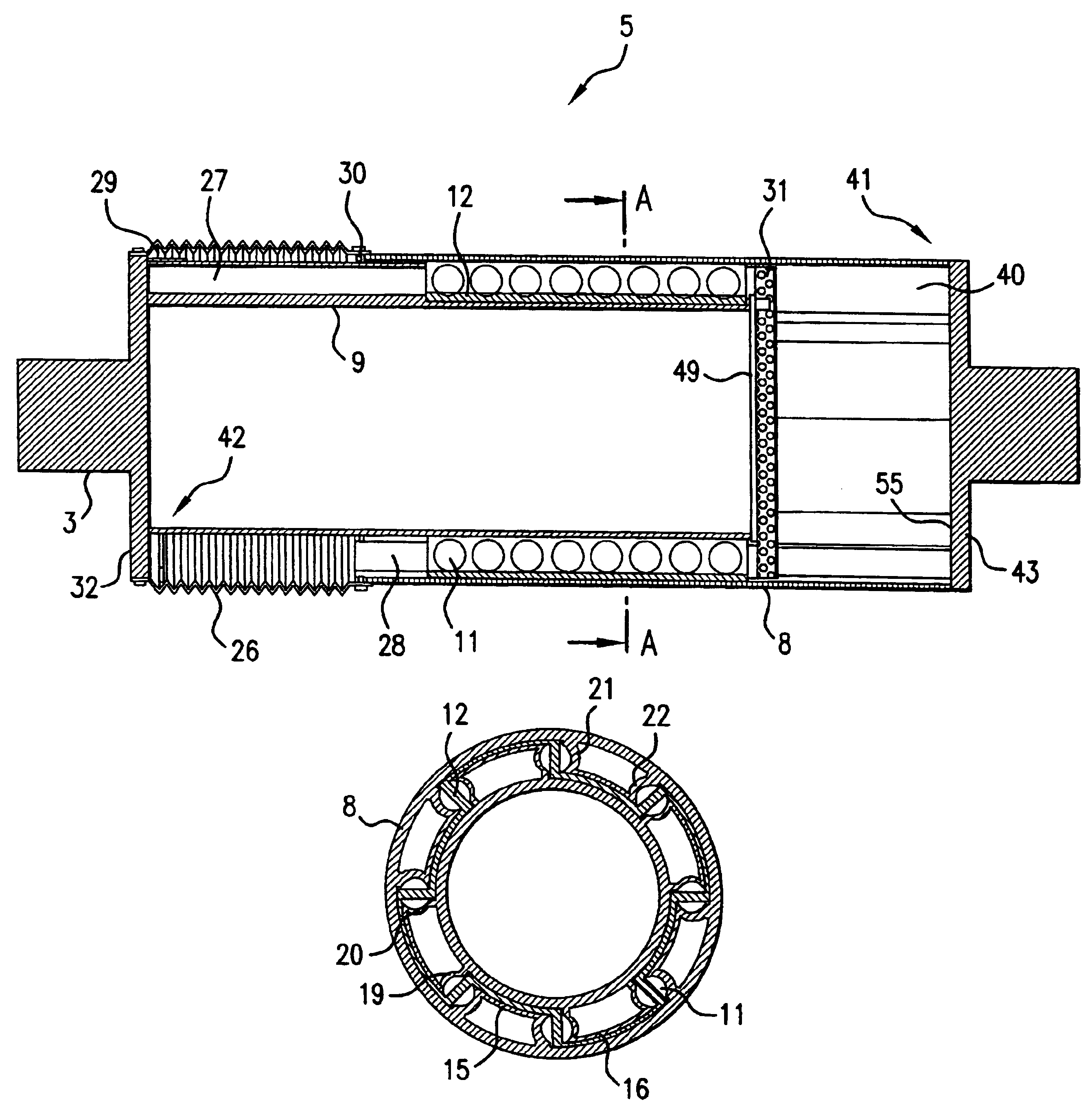
[0038]It can be further surveyed from FIG. 1 that the propeller shaft 3 is made of two pieces and is connected to the distributor gear, that is located in proximity to the engine and has not been illustrated in detail herein, by way of a swivel joint 50 on the one side and to a differential gear 45 through another swivel joint 4 on the other side. A further swivel joint 25, which is connected to an axially slidable shaft coupling 5 according to the invention, is moreover provided in the center between the two porti...


PUM


Abstract

A shaft coupling for a drive shaft (3), with a driving and a driven coupling component in which the driving or the driven coupling component is configured to form a cylindrical hollow coupling outer member (8) and the other coupling component configured to form a cylindrical coupling inner member (9), the two members being disposed so as to be coaxial with the longitudinal axis of the shaft coupling, and in which axially parallel grooves (27, 28) that are provided with right- and left-sided side walls (19, 20, 21, 22) are formed on the inner circumference of the coupling outer member (8) and on the outer circumference of the coupling inner member (9) for receiving rolling members (11) that drivingly and axially slidably interconnect the coupling outer member (8) and the coupling inner member (9), whereby the right- and left-sided side walls (19, 20, 21, 22) of the coupling inner member (8) and of the coupling outer member (9) are disposed side by side and mesh together thereby in such a manner that, together with a side wall (19, 20) of a groove (27) of the coupling inner member (9), a respective one of the side walls (21, 22) of a groove (28) of the outer member (8) defines and/or forms a rolling member passage (13, 14).

Description

BACKGROUND OF THE INVENTION[0001]The invention relates to a shaft coupling for an axially slidable drive shaft.[0002]Such a shaft coupling, which is known from DE 199 11 111 C1 for example, has an increased diameter cylindrical hollow tube end portion on the inner periphery of which axially parallel grooves are formed that serve to receive rolling members. An inner member of the cylindrical shaft coupling is disposed coaxially within said cylindrical hollow tube end portion, said inner member being provided, on the outer periphery thereof, with rolling member passages that are also oriented in an axially parallel manner and being connected, at the portion thereof pointing away from the tube end portion, to a constant velocity universal joint.[0003]The inner grooves of the hollow cylindrical tube end portion and outer grooves of the coupling inner member are oriented toward each other in such a manner that they are facing each other for the purpose of bearing together the rolling mem...

Claims


Application Information

Patent Timeline
IPC IPC(8): F16D3/02F16D3/06
CPCF16D3/065
Inventor AMBORN, PETERT
Owner AMBORN PETERT
Why Eureka
Try Eureka