Apparatus for conveying a light source to an intravenous needle to kill blood pathogens

a technology of light rays and apparatus, which is applied in the field of apparatus for conveying a light source to an intravenous needle to kill blood pathogens, can solve the problems that no apparatus has been developed for cleaning blood of pathogens such as fungi, viruses, bacteria and molds

Inactive Publication Date: 2005-06-21
DISTEFANO JOSEPH
View PDF15 Cites 67 Cited by
  • Summary
  • Abstract
  • Description
  • Claims
  • Application Information

AI Technical Summary

Problems solved by technology

In spite of the wide use of UV light by the medical profession no apparatus has been developed for cleansing blood of pathogens such as fungi, virus, bacteria and molds.

Method used


Image

  • Apparatus for conveying a light source to an intravenous needle to kill blood pathogens
  • Apparatus for conveying a light source to an intravenous needle to kill blood pathogens
  • Apparatus for conveying a light source to an intravenous needle to kill blood pathogens

Examples


Embodiment Construction

[0015]Throughout the following detailed description the same reference numerals refer to the same elements in all figures.

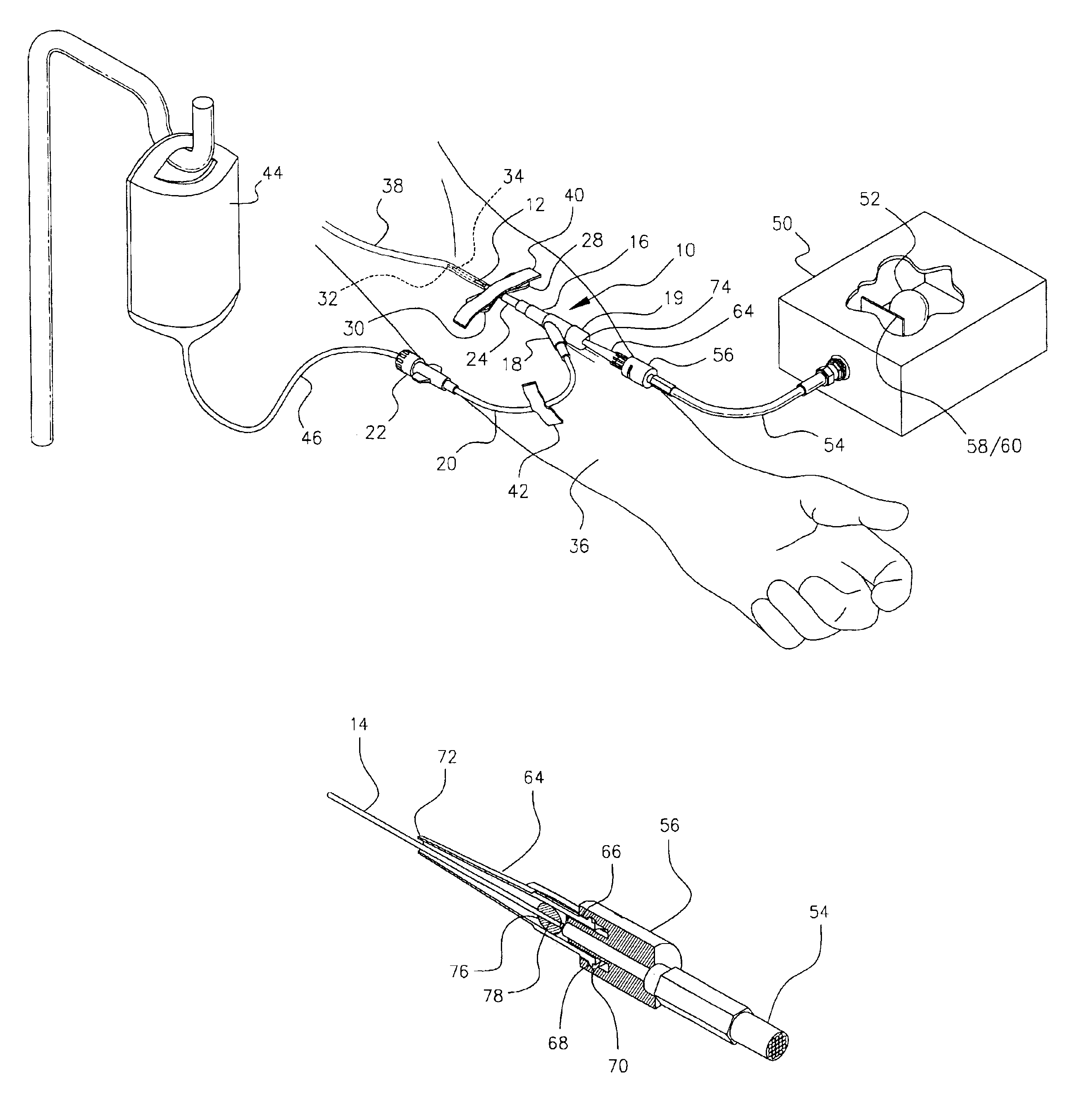
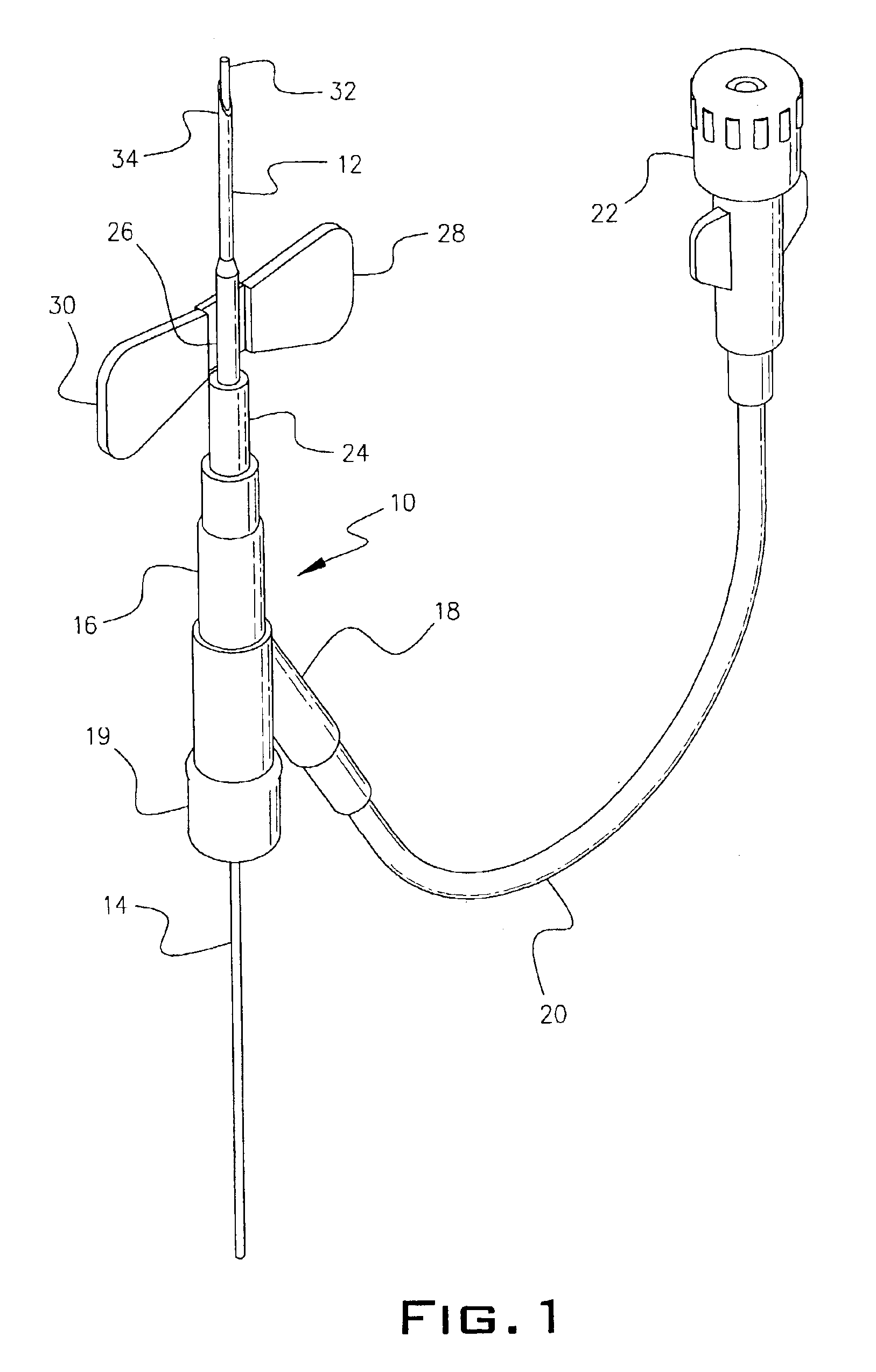
[0016]Referring first to FIG. 1, the housing 10 is a plastic disposable device in a Y-configuration having a first arm 18 and a second arm 19 leading to a cylindrical body 16. A quartz optic fiber 14 is threaded through the arm 19 of the housing 10. Arm 18 is connected to a pharmaceutically acceptable solution delivery conduit 20 from a connector 22. The cylindrical body 10 has a cylindrical end portion 24 receiving a hub 26 integral with butterfly wings 28 and 30. The hub 26 retains an upper portion of needle 12 in place. The optic fiber 14 is threaded from arm 19, through body 16 and through the needle 12 positioned in hub 26. An end 32 of the optic fiber 14 is visible at the tip 34 of needle 12.

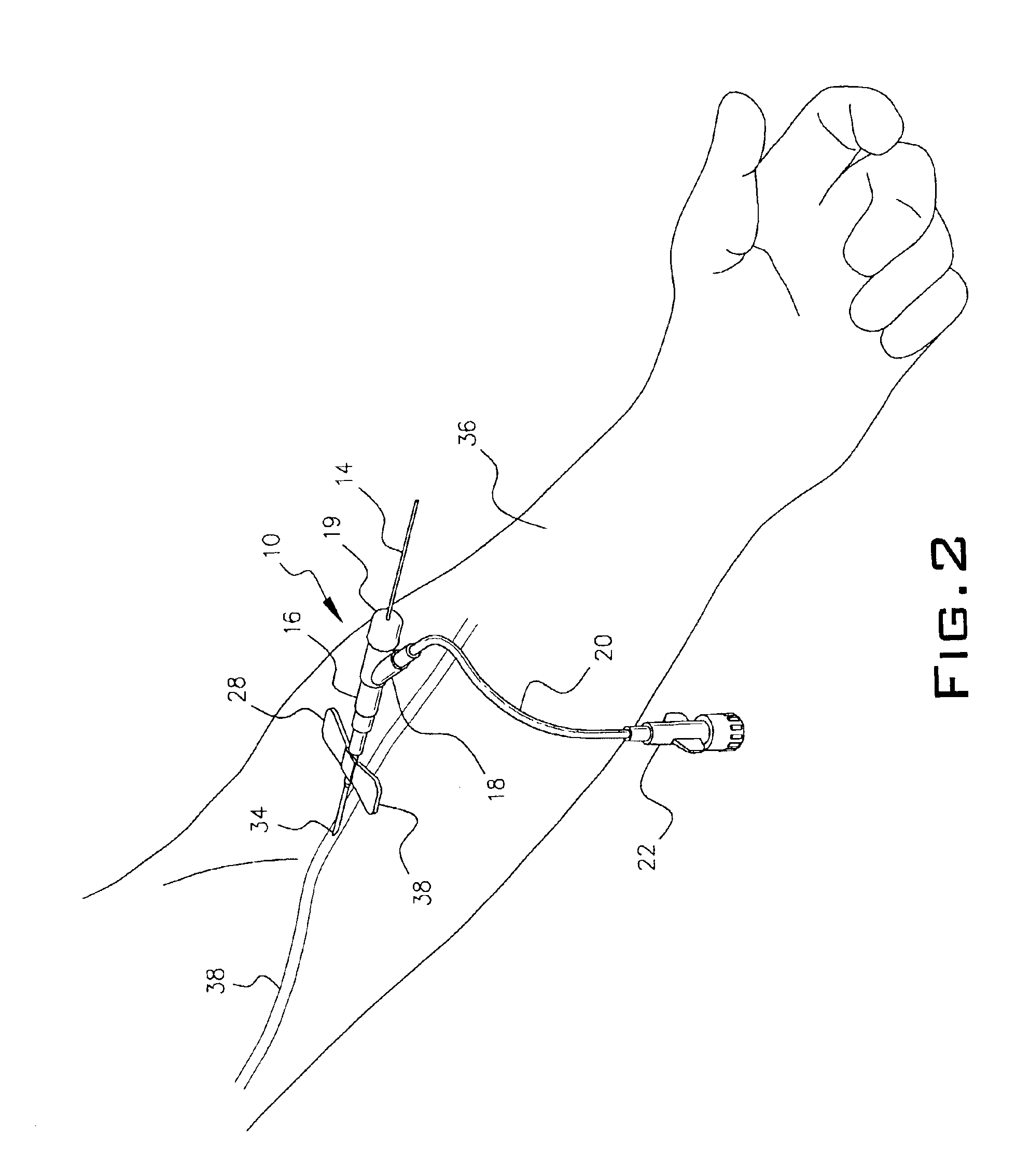
[0017]In FIG. 2 the arm 36 of a patient is shown with a vein 38 about to be penetrated by the point 34 of needle 12. After the needle 12 is inserted into vein 38 as sho...


PUM


Abstract

A tip of a needle is inserted into large vein of a patient. The needle is mounted in a butterfly device axially engaged to a generally cylindrical housing containing a Y-connector. A pharmaceutically acceptable solution is fed to the needle through the Y-connector to the housing. A quartz optic fiber is fed through the housing and needle to the tip of the needle in the patient's venous system. A source of UV and visible light directs both UV and visible light alternatively through the optic fiber to the patient's venous system to kill pathogens in the venous system.

Description

PRIOR APPLICATION[0001]This application is a continuation in part from application Ser. No. 09 / 940,996, filed Aug. 28, 2001 now abandoned.FIELD OF THE INVENTION[0002]This invention relates to an apparatus emitting light rays to kill pathogenic organisms. More particularly, it refers to an apparatus for the conveying of alternating UV and visible light through a quartz fiber optic cable to a needle inserted into a patient's venous blood.BACKGROUND OF THE INVENTION[0003]It is well known to use UV light to kill pathogens in water. Many systems exist to expose water to UV light with the object of destroying pathogens in the water. It also is well known to guide fiber optic instruments into arterial blood vessels. See U.S. Pat. No. 4,830,460 where the ultraviolet laser energy is used for the ablation of atherosclerotic plaque; U.S. Pat. No. 5,053,033 where an optical fiber delivers UV radiation to a blood vessel site following angioplasty to kill aortic smooth muscle cells at the site; U...

Claims


Application Information

Patent Timeline
Patent Type & Authority Patents(United States)
IPC IPC(8): A61B18/20A61B18/24A61M5/158A61M5/14A61B19/00
CPCA61B18/24A61M5/158A61M2205/053A61B2019/5206A61B2090/306
Inventor DISTEFANO, JOSEPH
Owner DISTEFANO JOSEPH
Why Eureka
Try Eureka