Eureka AIR delivers breakthrough ideas for toughest innovation challenges, trusted by R&D personnel around the world.

Capillary flow control in a fluidic diagnostic device

Inactive Publication Date: 2005-06-21
LIFESCAN IP HLDG LLC
View PDF27 Cites 132 Cited by
  • Summary
  • Abstract
  • Description
  • Claims
  • Application Information

AI Technical Summary

Benefits of technology

[0028]Devices of the present invention provide, in a capillary flow channel of the device, a stop junction that is angular in the flow direction. Such a stop junction can be designed with readily-controlled break-through pressure. Note that in the present specification and the figures, capillaries are shown bound

Problems solved by technology

Since diabetes can cause dangerous anomalies in blood chemistry, it can contribute to vision loss, kidney failure, and other serious medical consequences.

Method used


Image

  • Capillary flow control in a fluidic diagnostic device
  • Capillary flow control in a fluidic diagnostic device
  • Capillary flow control in a fluidic diagnostic device

Examples


Embodiment Construction

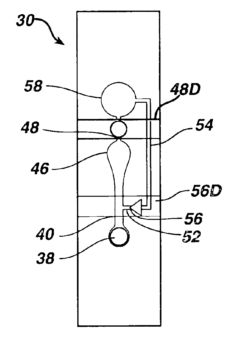
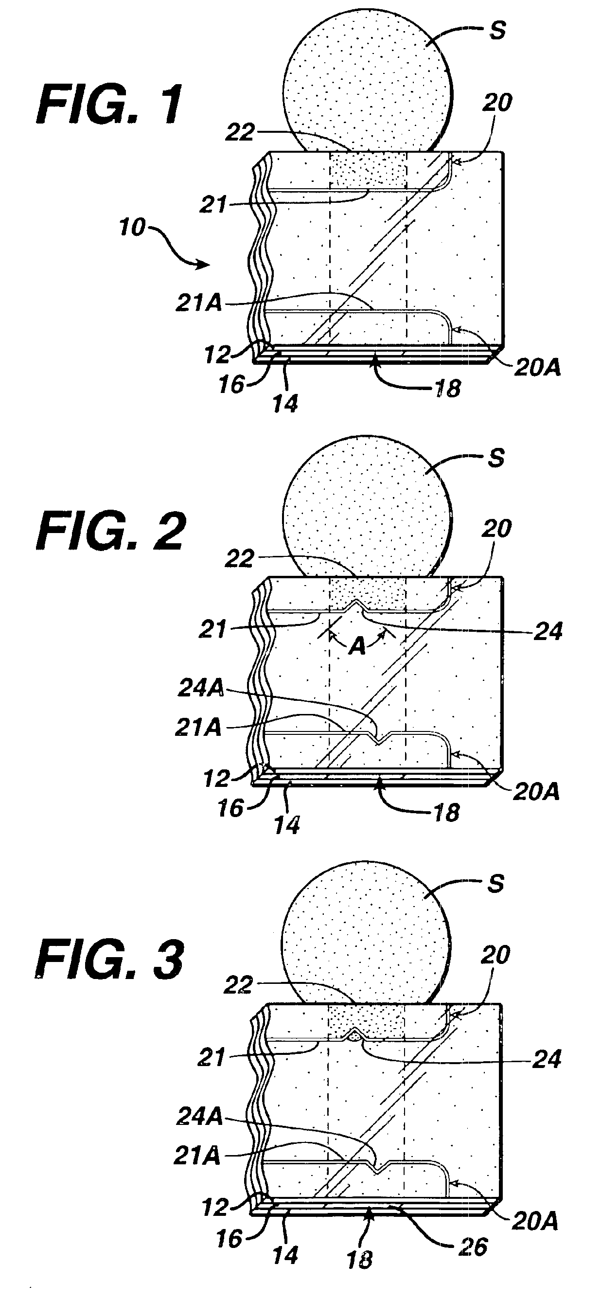
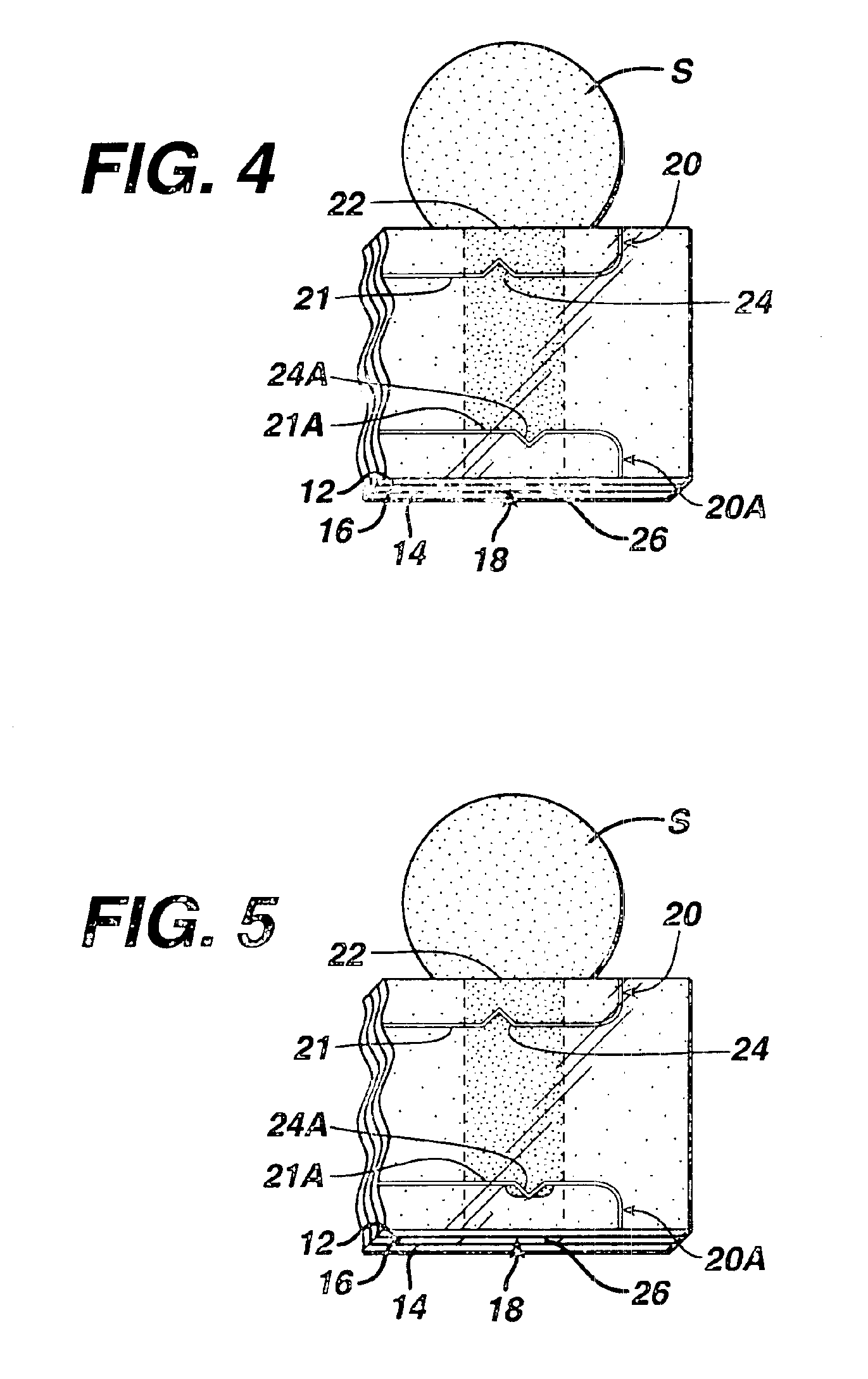
[0035]When fluid flows through a channel, a discontinuity in channel cross section can form a “stop junction,” which can stop the fluid flow, as described in U.S. Pat. Nos. 4,426,451; 5,230,866; and 5,912,134, incorporated herein by reference. The stop junction results from surface tension that creates a back pressure that stops the fluid meniscus from proceeding through the discontinuity. The stop junction is weakened, and flow thereby enhanced, when the leading edge of the meniscus encounters the vertex of an acute angle and is then stretched along the arms of the angle. This may be described as the angle “pointing” in a direction opposite to the direction of fluid flow.

[0036]This invention relates to a medical diagnostic device that has a flow channel with a stop junction. The stop junction is angular in the direction of flow, which permits fluid in the channel to break through the stop junction when there is a predetermined pressure difference across the stop junction. The advan...


PUM


Abstract

A medical diagnostic device for measuring an analyte concentration or property of a biological fluid includes capillary flow channels to convey a sample of the fluid from an inlet to a branching point, and then to a measurement area and, alternatively, through a bypass channel to an overflow region. A first stop junction stops fluid flow after it enters the measurement area. The bypass channel has a capillary dimension in at least one direction. A second stop junction, in the bypass channel, has boundary region that has a dimension that is greater in that direction and forms an angle that points toward the branching point. With this construction, the second stop junction initially prevents flow to the overflow region, but permits the flow after the measurement area is filled. The device is particularly suited for measuring coagulation time of blood.

Description

CROSS-REFERENCE TO PRIOR APPLICATION[0001]This application relates to U.S. application Ser. Nos. 09 / 333,765, filed Jun. 15, 1999 , now U.S. Pat. No. 6,521,182, issued on Feb. 18, 2003; and 09 / 354,995, filed Jul. 16, 1999, now U.S. Pat. No. 6,084,660, issued on Jul. 4, 2000.BACKGROUND OF THE INVENTION[0002]1. Field of the Invention[0003]This invention relates to a medical diagnostic device that includes an element for controlling fluid flow through the device; more particularly, to a device that facilitates fluid flow through a stop junction.[0004]2. Description of the Related Art[0005]A variety of medical diagnostic procedures involve tests on biological fluids, such as blood, urine, or saliva, to determine an analyte concentration in the fluid. The procedures measure a variety of physical parameters—mechanical, optical, electrical, etc.,—of the biological fluid.[0006]Among the analytes of greatest interest is glucose, and dry phase reagent strips incorporating enzyme-based composit...

Claims


Application Information

Patent Timeline
IPC IPC(8): G01N33/49A61B5/00G01N33/86B01L3/00G01N27/28G01N27/416
CPCG01N33/4905Y10T436/2575G01N33/538
Inventor SHARTLE, ROBERT JUSTICE
Owner LIFESCAN IP HLDG LLC
Why Eureka
Eureka Blog
Learn More