Interlace motion artifact detection using vertical frequency detection and analysis

a technology of vertical frequency detection and analysis, applied in the field of video image processing, can solve the problems of interlaced motion artifacts, inaccurate detection, and erroneous detection of high frequencies in certain cases, and achieve the effect of preserving the maximum amount of vertical detail and reducing artifacts

Inactive Publication Date: 2005-06-21
LATTICE SEMICON CORP
View PDF78 Cites 30 Cited by
  • Summary
  • Abstract
  • Description
  • Claims
  • Application Information

AI Technical Summary

Benefits of technology

[0018]The present invention advantageously allows for the reduction of artifacts in deinterlaced video images. By correctly and accurately identifying interlace motion artifacts, a video deinterlacer can combine pixels from two fields in areas which do not have motion artif

Problems solved by technology

However, where motion exists in the image, two adjacent fields cannot simply be combined without generating interlace motion artifacts since the fields are not temporally consistent in those areas (with motion).
While the latter frequency-based method does detect interlace mot

Method used


Image

  • Interlace motion artifact detection using vertical frequency detection and analysis
  • Interlace motion artifact detection using vertical frequency detection and analysis
  • Interlace motion artifact detection using vertical frequency detection and analysis

Examples


Embodiment Construction

[0025]A method and apparatus for accurate detection of interlace motion artifacts by vertical frequency analysis is disclosed. In the following description, numerous specific details are set forth in order to provide a thorough understanding of the present invention. It will be understood however that the present invention may be practiced without some or all of these specific details. In other instances, well known process operations have not been described in detail in order not to unnecessarily obscure the present invention.

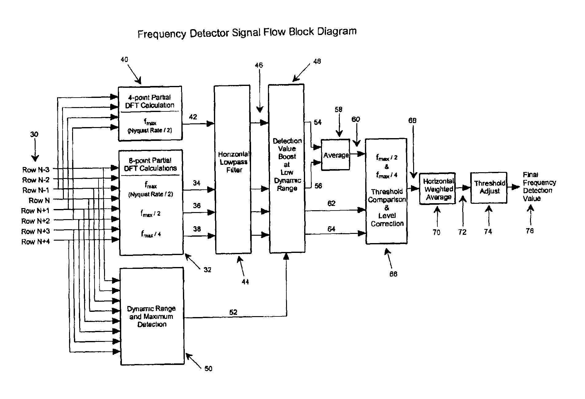
[0026]In a preferred embodiment of the invention, at each pixel location for which a detection of interlaced motion artifacts is needed, calculations for the detection of two specific lower frequencies are performed, along with two calculations for fmax over two varying sample set sizes. A signal flow block diagram of the invention is shown in FIG. 3. Eight vertically aligned luma data samples 30 from a frame formed from the merging of two adjacent fields are ...


PUM


Abstract

An interlace motion artifact detector which identifies video image spatial frequencies characteristic of motion artifacts. The detected frequency is the maximum which can be represented by the vertical sampling rate of the video format (i.e., the Nyquist frequency). This frequency is detected by a pair of partial Discrete Fourier Transforms (DFT) which each calculate only the frequency component of interest. Additional vertical frequency components at one half and one quarter the interlace motion artifact frequency are also detected via a partial DFT. The presence of these lower frequencies acts as an indication of an erroneous motion artifact detection. Additionally, the dynamic range and maximum level of the video data is used as an indication of when to boost the frequency detection levels in areas of low brightness and/or contrast.

Description

[0001]The present application is a continuation-in-part of U.S. patent application Ser. No. 09 / 372,713, filed on Aug. 11, 1999 now U.S. Pat. No. 6,489,998 entitled “Method and Apparatus for Detecting Frequency in Digital Video Images”, assigned to the assignee of the present application, which is incorporated herein by reference.BACKGROUND OF THE INVENTION[0002]1. Field of the Invention[0003]The present invention relates generally to the processing of video images and more particularly to techniques for deinterlacing video images.[0004]2. Description of the Related Art[0005]The world's major television standards use a raster scanning technique known as “interlacing.” Interlaced scanning draws horizontal scan lines from the top of the screen to the bottom of the screen in two separate passes, one for even numbered scan lines and the other for odd numbered scan lines. Each of these passes is known as a field.[0006]It is often necessary and / or desirable to convert an interlaced video s...

Claims


Application Information

Patent Timeline
IPC IPC(8): H04N5/21H04N5/44G09G5/39G09G5/393
CPCH04N5/144H04N5/208H04N9/8042H04N5/775H04N7/0112H04N7/012H04N5/21G09G5/39G09G5/393G09G2310/0229H04N5/14H04N5/4401H04N5/66H04N5/85H04N21/44008H04N21/426
Inventor ADAMS, DALE R.
Owner LATTICE SEMICON CORP
Why Eureka
Try Eureka