Method and apparatus for phase correlation holographic drive

a holographic drive and phase correlation technology, applied in the field of holographic storage, can solve the problems of unsuitable holographic drives using such transmission type architectures, unsuitable holographic drives for popular applications, and introduction of other undesirable features

Inactive Publication Date: 2005-06-21
AKONIA HOLOGRAPHICS
View PDF19 Cites 70 Cited by
  • Summary
  • Abstract
  • Description
  • Claims
  • Application Information

AI Technical Summary

Benefits of technology

[0016]In a method of managing data using a storage medium in accordance with the present invention, a reference beam and a signal beam are generated. The signal beam includes the information to be managed. The reference beam is phase correlation beam and a holographic medium is provided which has a reflective surface. The signal beam and reference beam then interfere in the holographic medium to create a phase-correlation hologram therein. On reconstruction the reconstructed signal (output) beam is in a different angular bandwidth than the directly reflected reference beam allowing the filter / mirror to physically separate the signal from the noise generated by the reference beam.

Problems solved by technology

One drawback with the Tamarack design is that it uses a transmission geometry.
As such, this type of architecture requires space on both sides of the holographic media which generally requires a relatively large volume.
Thus, a holographic drive using such a transmission type architecture may be unsuitable for popular applications where relatively compact data storage is desirable, such as desktop or laptop computers.
However, in doing so, some other undesirable features are introduced.
That is, holograms that are at adjacent locations to a target hologram (e.g., a hologram that is being read) can generate interference when reading the target hologram.
Such interference can lower the signal to noise ratio in the readout signal of the target holograms and ultimately lead to errors or severely limit the achievable density.
This problem can be exacerbated by the fact that the signal and reference beams share the same angular bandwidth because beams near a center axis of the system will create holograms having very low selectivity.

Method used


Image

  • Method and apparatus for phase correlation holographic drive
  • Method and apparatus for phase correlation holographic drive
  • Method and apparatus for phase correlation holographic drive

Examples


Embodiment Construction

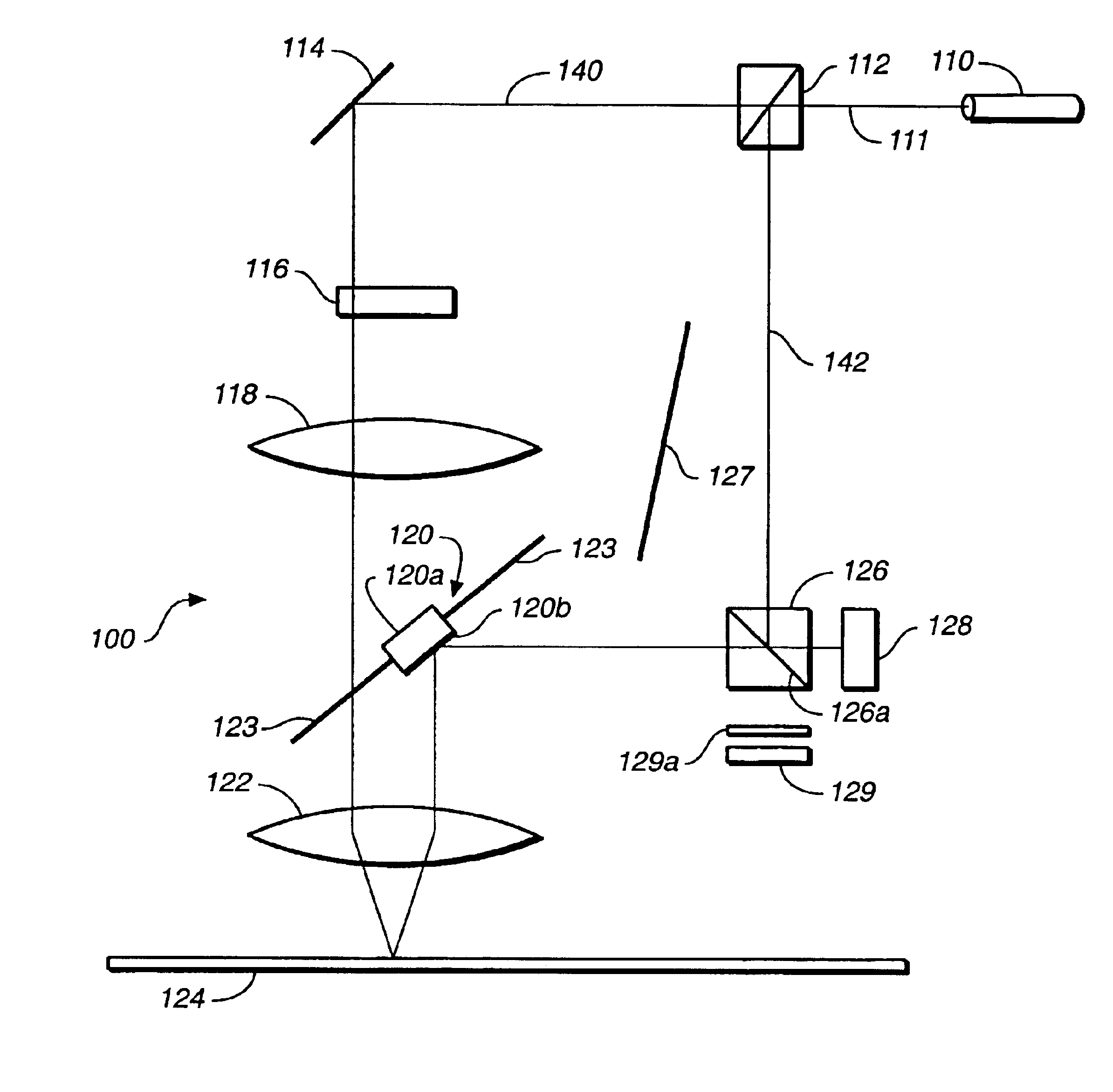
[0033]A system and method for storing and reading out holographic information in a drive format in accordance with the present invention preferably uses a reflective holographic recording medium. As such, all the recording and reading optics can be located on one side of the recording medium. Thus, a holographic storage drive of the present invention can be advantageously more compact than a drive using a transmission configuration which would include optics on both sides of the recording medium. Additionally, the holographic storage drive of the present invention uses phase-correlation holography and preferably filters out low spatial frequency components of the reference beam. As such relatively high selectivity between holograms can be advantageously achieved, even in a configuration in which reference and signal beams are incident on the holographic recording medium at angles at or near the normal to the media surface. Also, in a holographic storage drive in accordance with the ...


PUM

PropertyMeasurementUnit
angleaaaaaaaaaa
focal lengthsaaaaaaaaaa
angleaaaaaaaaaa

Abstract

A holographic storage apparatus for recording data in a holographic medium includes at least one light source for generating a reference beam and a signal beam. The reference beam is preferably a phase beam of unchanging phase content. The apparatus also includes a holographic medium placed in a path of the reference beam and a path of the signal beam. The holographic medium has a first face and both the reference beam and the signal beam enter the holographic medium through the first face. The holographic medium also includes a data reflective surface. The reference beam and the signal beam interfere in the holographic medium to create a hologram only after at least one of the reference beam and the signal beam have reflected off of the data reflective surface.

Description

RELATED APPLICATIONS[0001]The present application claims priority to U.S. Provisional Patent Application No. 60 / 309,202, filed Jul. 31, 2001, entitled “Holographic Drive and Media Architecture” by Kevin R. Curtis, and incorporates that provisional application by reference.TECHNICAL FIELD[0002]The present invention relates to holographic storage. More specifically, the present invention relates to a system and method for storing phase correlation multiplexed holograms in a holographic medium.BACKGROUND[0003]Holographic memory systems involve the three-dimensional storage of holographic representations (i.e. holograms) of data elements as a pattern of varying refractive index and / or absorption imprinted in the volume of a storage medium such as a crystal of lithium niobate. Holographic memory systems are characterized by their high density storage potential and the potential speed with which the stored data is randomly accessed and transferred.[0004]In general, holographic storage mem...

Claims


Application Information

Patent Timeline
Patent Type & Authority Patents(United States)
IPC IPC(8): G11B7/0065G11B7/00
CPCG11B7/0065G03H2001/2675G11B2007/0006
Inventor CURTIS, KEVIN R.
Owner AKONIA HOLOGRAPHICS
Why Eureka
Try Eureka