
Method of consecutive writing on recordable disc

a recording media and recording method technology, applied in the field of recording methods and recording apparatuses for disctype recording media, can solve the problems of reading errors during playback from time to time, and affecting the quality of the recording

Inactive Publication Date: 2005-06-21
YAMAHA CORP
View PDF4 Cites 22 Cited by
  • Summary
  • Abstract
  • Description
  • Claims
  • Application Information

AI Technical Summary

Benefits of technology

[0011]The present invention has been made with a view of the above problems, and it is an object thereof to provide a recording method and a recording apparatus for disc type recording media such as optical discs and other various types of recording media, that permits additional writing to be achieved continuously. When new information is additionally written, following a recording end of previous information, there will be less disturbance in synchronization at an additional writing position during reproduction.

Problems solved by technology

Otherwise, there may be a disagreement in phase between frames of the previously recorded information and the newly added information.
In such a case, synchronization will be disturbed at the additional writing position with a resultant read error when the recorded information is reproduced after adding the new information.
When the disc that contains the additional writing is reproduced, the synchronization will be disturbed at the additional writing position, leading to a read error during the reproduction from time to time.
Hence, when the disc in which additional writing has been performed is played back, the synchronization is disturbed at the additional writing position, resulting in a read error during playback from time to time.
However, the oscillation frequency of a VCO varies when additional writing is begun, causing synchronization to be disturbed at an additional writing position, leading to a possibility of the occurrence of a read error during reproduction.

Method used


Image

  • Method of consecutive writing on recordable disc
  • Method of consecutive writing on recordable disc
  • Method of consecutive writing on recordable disc

Examples


first embodiment

(First Embodiment)

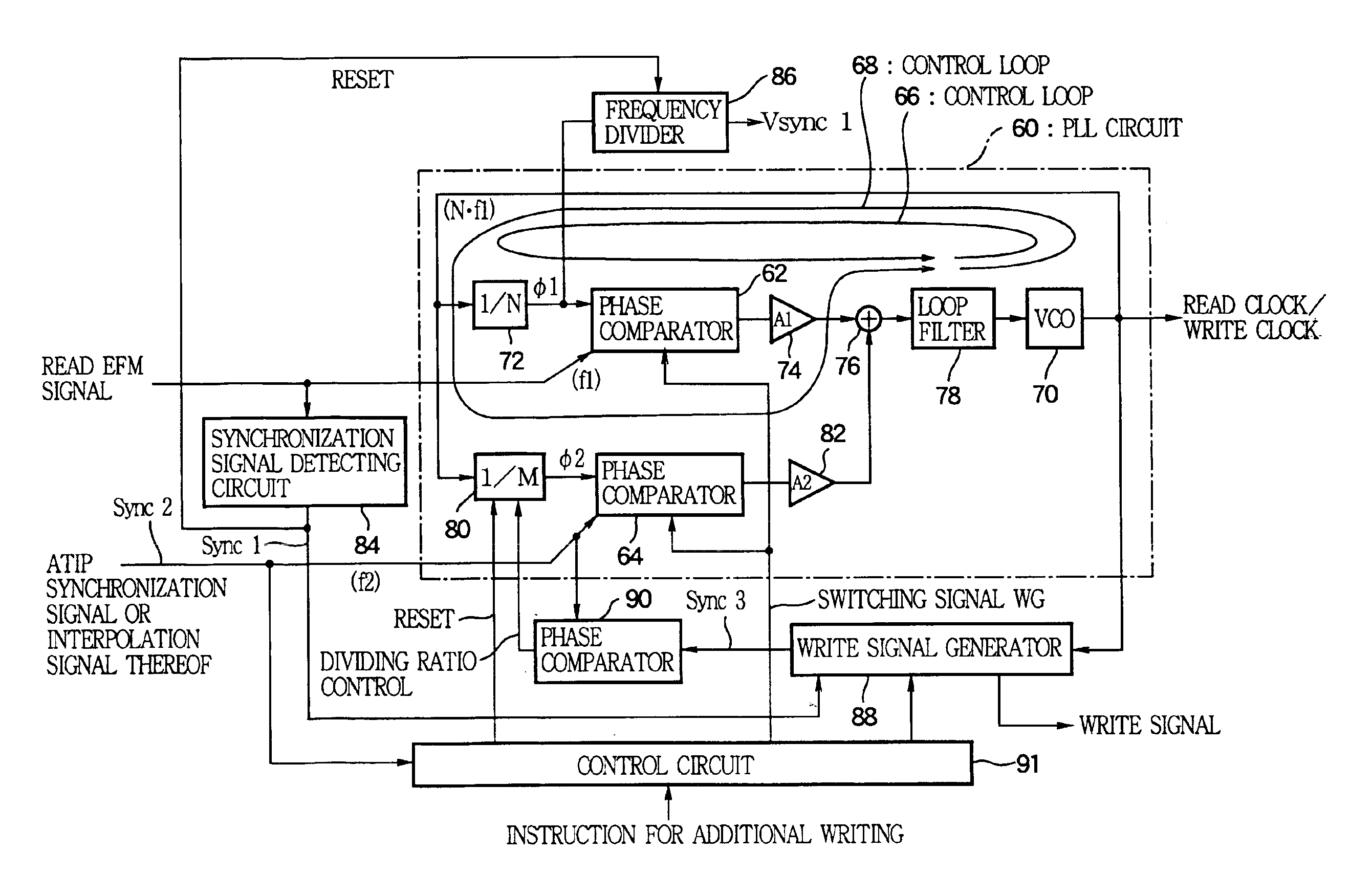
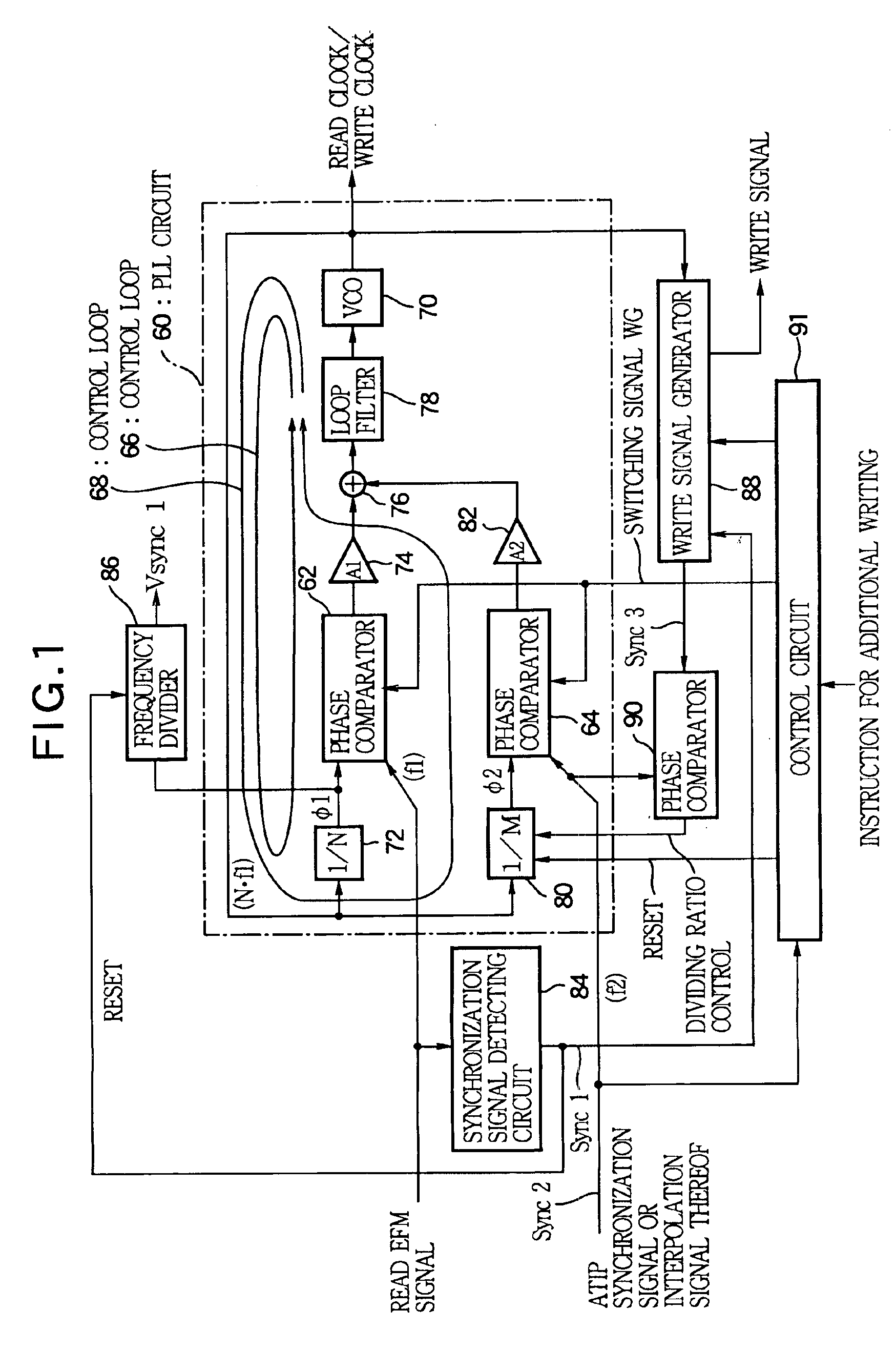
[0042]A first embodiment in which the present invention has been applied for recording onto a CD-R / RW disc will be described. FIG. 1 shows the configuration of an essential section of a CD-R / RW drive (a disc drive unit capable of writing to and reading from a CD-R disc and a CD-RW disc) to which the present invention has been applied. The CD-R / RW drive is designed to permit read clocks and write clocks to be produced by a single phase-locked loop circuit 60. The phase-locked loop circuit 60 is provided with a control loop 66 that passes through a phase comparator 62 and a control loop 68 that passes through a phase comparator 64. By a switching signal WG, the phase comparator 62 is turned ON and the phase comparator 64 is turned OFF so as to turn ON the control loop 66 and turn OFF the control loop 68, or the phase comparator 62 is turned OFF and the phase comparator 64 is turned ON so as to turn OFF the control loop 66 and turn ON the control loop 68.

[0043]The con...

second embodiment

(Second Embodiment)

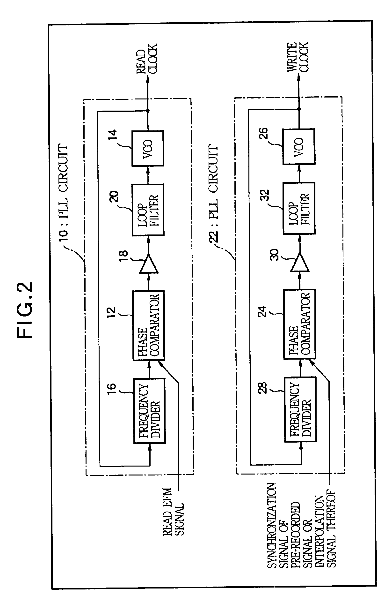
[0052]A second embodiment in which the present invention has been applied to recording in a CD-R / RW disc will be described. FIG. 8 shows the configuration of an essential section of a CD-R / RW drive to which the present invention has been applied. In this, a read clock producing phase-locked loop circuit 102 and a write clock producing phase-locked loop circuit 104 are separately constructed. According to this configuration, it is possible to design phase-locked loop circuits dedicated for producing read clocks and for producing write clocks, respectively, so that circuits that stably operate can be implemented.

[0053]The phase-locked loop circuit 102 will be described. A phase comparator 106 compares the phase of a read EFM signal read from the CD-R / RW disc and the phase of a signal obtained by dividing, in a predetermined manner, an oscillation clock of a VCO 108 by a frequency divider 111 constructed by a counter or the like. An amplifier 113 imparts a predetermi...

third embodiment

(Third Embodiment)

[0062]A third embodiment in which the present invention has been applied to recording in a CD-R / RW disc will be described. FIG. 9 shows the configuration of an essential section of a CD-R / RW drive to which the present invention has been applied. In this, a read clock producing phase-locked loop circuit 147 and a write clock producing phase-locked loop circuit 149 are separately constructed. The write clock producing phase-locked loop circuit 149 has one control loop, and the input of its phase comparator 151 is switched.

[0063]The phase-locked loop circuit 147 will be described. A phase comparator 153 compares the phase of a read EFM signal read from the CD-R / RW disc and the phase of a signal obtained by dividing, in a predetermined manner, an oscillation clock of a VCO 161 by a frequency divider 155 constructed by a counter or the like. An amplifier 157 imparts a predetermined gain A0 to an output of the phase comparison, and the output is supplied to a control inp...


PUM


Abstract

A method is designed for writing new information subsequently to an end of previous information written in a track of a record medium having a pre-recorded signal along the track. The method is carried out by the steps of reading a part of the previous information including the end thereof to generate a read signal divided into a sequence of frames, start generating of a write signal in synchronization with a phase of the last frame of the read signal at the end of the previous information to thereby write the new information continuously from the end of the previous information, and then shifting a period of a frame of the write signal relative to a period of a synchronization signal contained in the pre-recorded signal, thereby gradually adjusting a phase of the frame of the write signal to a phase of the synchronization signal of the pre-recorded signal.

Description

BACKGROUND OF THE INVENTION[0001]The present invention relates to a recording method and a recording apparatus for a disc-type recording media such as an optical disc and other diverse types of recording media The present invention makes it possible to achieve next information to be written continuously from a recording end of previously recorded information, such that there will be less disturbance in synchronization at a write splicing position between the previous information and the subsequent information during reproduction.[0002]When new information is additionally written, following a recording end of previous information in a successive recording type medium such as a recordable or rewritable optical disc, there may be a discontinuous state where a frequency of the recorded signal and a bit clock for reading of the recorded information do not coincide with each other. Otherwise, there may be a disagreement in phase between frames of the previously recorded information and th...

Claims


Application Information

Patent Timeline
IPC IPC(8): G11B27/19G11B27/30G11B20/14G11B27/24G11B27/034G11B20/10G11B27/031H03L7/08H03L7/087H04L7/033
CPCG11B20/10009G11B20/10425G11B27/24G11B27/3027G11B2220/41G11B2220/218G11B2220/2545G11B2220/2562G11B2220/2575G11B2220/216
Inventor MORISHIMA, MORITO
Owner YAMAHA CORP
Learn More