Apparatus and method for inspecting and marking repair areas on a blade

a technology for inspecting blade damage and marking repair areas, applied in the direction of instruments, machines/engines, liquid fuel engines, etc., can solve the problems of affecting the performance of engines, affecting the accuracy of blade inspection, so as to improve the aerodynamic efficiency of the blade, improve the accuracy of visual inspection of damaged areas, and relieve the effect of blade stress points

Inactive Publication Date: 2005-06-28
LOCKHEED MARTIN CORP
View PDF18 Cites 36 Cited by
  • Summary
  • Abstract
  • Description
  • Claims
  • Application Information

AI Technical Summary

Benefits of technology

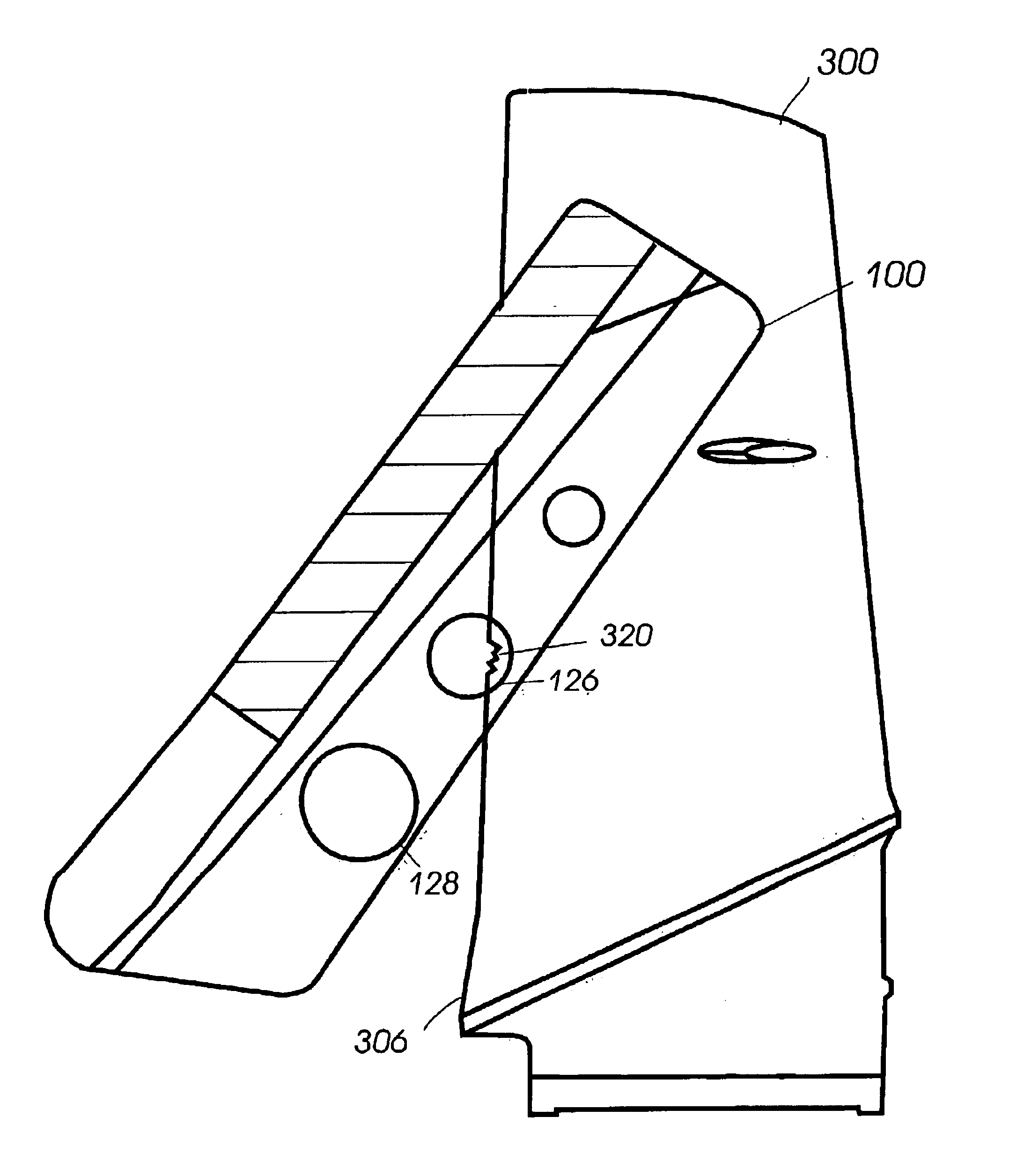
[0013]Against this background of known technology, an apparatus for assessing damaged areas on a blade includes a set of marks indicating the maximum areas of damage allowed on a blade. A profile guide enables the inspector to align the template in proper position against the blade for accurate visual inspection of the damaged areas. One or more blend guides are included to allow the inspector to mark a blend area around damage within the allowable limits, and to enable maintenance personnel to smooth sharp, jagged edges of the damaged areas, thereby relieving stress points on the blade and improving the aerodynamic efficiency of the blade. The template is fabricated with transparent material that allows the blade to be viewed when the template is overlayed on the blade.

Problems solved by technology

The blades rotate at very high speeds, and various levels of damage can be inflicted by foreign objects striking the blades, depending on the speed of the blades, the speed of the aircraft, and the size and hardness of the object.
Additionally, leading and trailing edges of blades are subject to gradual erosion from abrasive sand and grit particles in the air that is ingested by the engine during operation.
Damaged and eroded blades degrade engine performance, as well as posing a potential cause of engine failure, and therefore must be replaced once the damage or erosion has exceeded a certain level.
The flight crew is often not aware of FOD, however, in case of extensive damage, it can be indicated by vibration and changes in the engine's normal operating parameters.
It is often difficult to visually gauge the amount of a blade that is missing without a measuring aid, such as a ruler.
The contour can add to the difficulty of measuring the blade with a conventional straightedge ruler.
Additionally, fan and compressor blades are typically tapered along their length from root to tip, further adding to the difficulty of determining whether the damage is within allowable limits.
The problem is exacerbated on aircraft with inlet ducts, which do not allow easy access to inspect the blades.
The blade inspection procedure outlined above is awkward, time-consuming, and prone to human error.

Method used


Image

  • Apparatus and method for inspecting and marking repair areas on a blade
  • Apparatus and method for inspecting and marking repair areas on a blade
  • Apparatus and method for inspecting and marking repair areas on a blade

Examples


Embodiment Construction

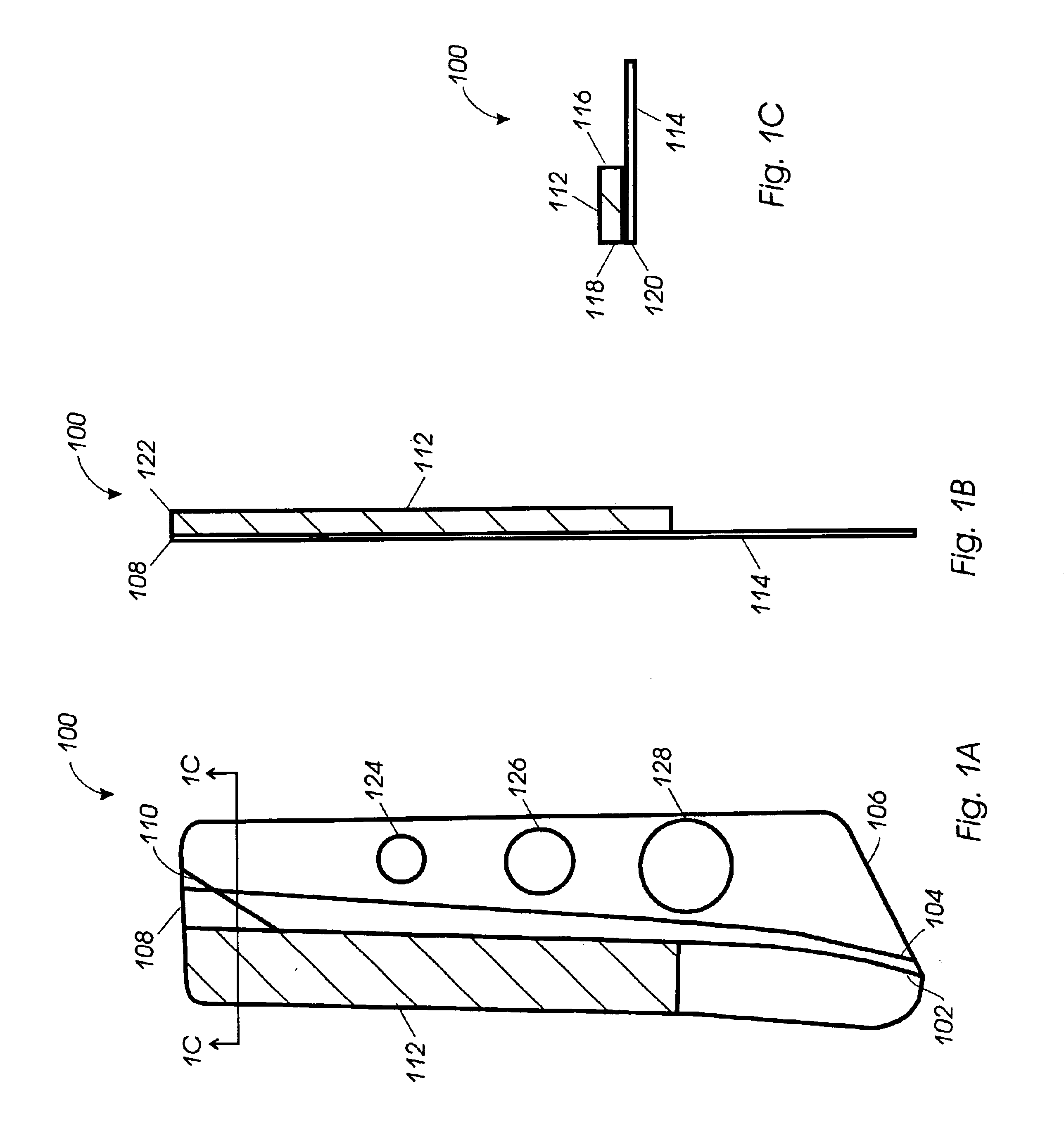
[0029]Referring to FIGS. 1A through 1C, FIG. 1A shows a front view of an embodiment of template 100, which can be used to determine whether damage or erosion extends beyond allowable limits on virtually any type of blade. Template 100 is typically sized and shaped to substantially conform to at least a portion of the blade being inspected and includes one or more marks that indicate the maximum areas of damage allowed on any part of the blade, such as one or both of leading and trailing edges as well as the tip of a blade.

[0030]In the embodiment of template 100 shown in FIG. 1A, alignment mark 102 is provided to allow the inspector to align template 100 with at least a portion of the blade being inspected. When alignment mark 102 of template 100 is aligned with the corresponding portion of the blade, damage limit mark 104 provides an indication of the amount of the blade that can be damaged or eroded before the blade must be replaced. In the embodiment shown, damage that extends bet...


PUM

PropertyMeasurementUnit
thickaaaaaaaaaa
thickaaaaaaaaaa
shapeaaaaaaaaaa

Abstract

A template for assessing damaged areas on a blade includes a set of marks indicating the maximum areas of damage allowed on an edge, as well as the tip of a blade. A guide enables the template to be aligned in proper position against the blade for accurate visual inspection of the damaged areas. One or more blend guides are included to allow the inspector to mark a blend area around the damage to enable maintenance personnel to smooth sharp, jagged edges of the damaged areas, thereby relieving stress points on the blade and improving the aerodynamic efficiency of the blade. The template is fabricated with transparent material that allows the blade to be viewed when the template is overlayed on the blade. A mechanism such as a clip, a sleeve, or magnetic attraction can be included on the template to retain the template on the blade during inspection.

Description

STATEMENT OF GOVERNMENT INTEREST[0001]The invention was made with Government support under contract F33657-98-D-0117, awarded by the U.S. Government. The U.S. Government has certain rights in this invention.BACKGROUND[0002]1. Technical Field[0003]The present invention relates to geometrical instruments, and more particularly to a template for inspecting blade damage and marking the damaged area for repair.[0004]2. Description of the Related Art[0005]Foreign object damage (FOD) on aircraft turbine engine blades is a condition defined as any damage from small nicks and scratches to complete disablement or destruction of an engine caused by damaged parts of blades that break loose during operation. The blades rotate at very high speeds, and various levels of damage can be inflicted by foreign objects striking the blades, depending on the speed of the blades, the speed of the aircraft, and the size and hardness of the object.[0006]FOD can be caused in a variety of ways including rocks o...

Claims


Application Information

Patent Timeline
Patent Type & Authority Patents(United States)
IPC IPC(8): F01D5/00F01D21/00F04D29/32
CPCB23P6/002F01D5/005F01D21/003F04D29/324F05D2230/80Y02T50/673F05D2260/80Y02T50/60
Inventor HOLDER, PAUL F.
Owner LOCKHEED MARTIN CORP
Why Eureka
Try Eureka