Method for operating an internal combustion engine especially of a motor vehicle

a technology of internal combustion engine and motor vehicle, which is applied in the direction of electric control, machines/engines, mechanical equipment, etc., can solve the problem of not being able to supply additional air to the combustion chamber

Inactive Publication Date: 2005-06-28
ROBERT BOSCH GMBH
View PDF13 Cites 2 Cited by
  • Summary
  • Abstract
  • Description
  • Claims
  • Application Information

AI Technical Summary

Benefits of technology

[0007]It is an object of the invention to provide a method wherein the catalytic converter is in the position to purify the exhaust gas as optimally as possible even after a longer overrun phase.
[0009]With the recirculation of exhaust gas during overrun operation, it is achieved that the hot exhaust gas does not completely leave the internal combustion engine; rather, the exhaust gas at least partially forms a loop in the internal combustion engine. In this way, the temperature of the exhaust gas within the internal combustion engine becomes less only slowly even though no new hot exhaust gas is added because of the missing combustion of fuel in overrun operation. The temperature of the catalytic converter therefore is substantially maintained and the catalytic converter does not cool or at least does not cool out so rapidly.
[0010]In an advantageous embodiment of the invention, less air is supplied to the combustion chamber during overrun operation. In this way, cool fresh air is prevented from reaching the combustion chamber of the internal combustion engine which would have the consequence of reducing the temperature, inter alia, of the exhaust gas. In this way, it is achieved that the temperature of the exhaust gas present is at least not so reduced that the catalytic converter is cooled out. If required, no additional air can be supplied to the combustion chamber in overrun operation.

Problems solved by technology

If required, no additional air can be supplied to the combustion chamber in overrun operation.

Method used


Image

  • Method for operating an internal combustion engine especially of a motor vehicle
  • Method for operating an internal combustion engine especially of a motor vehicle
  • Method for operating an internal combustion engine especially of a motor vehicle

Examples


Embodiment Construction

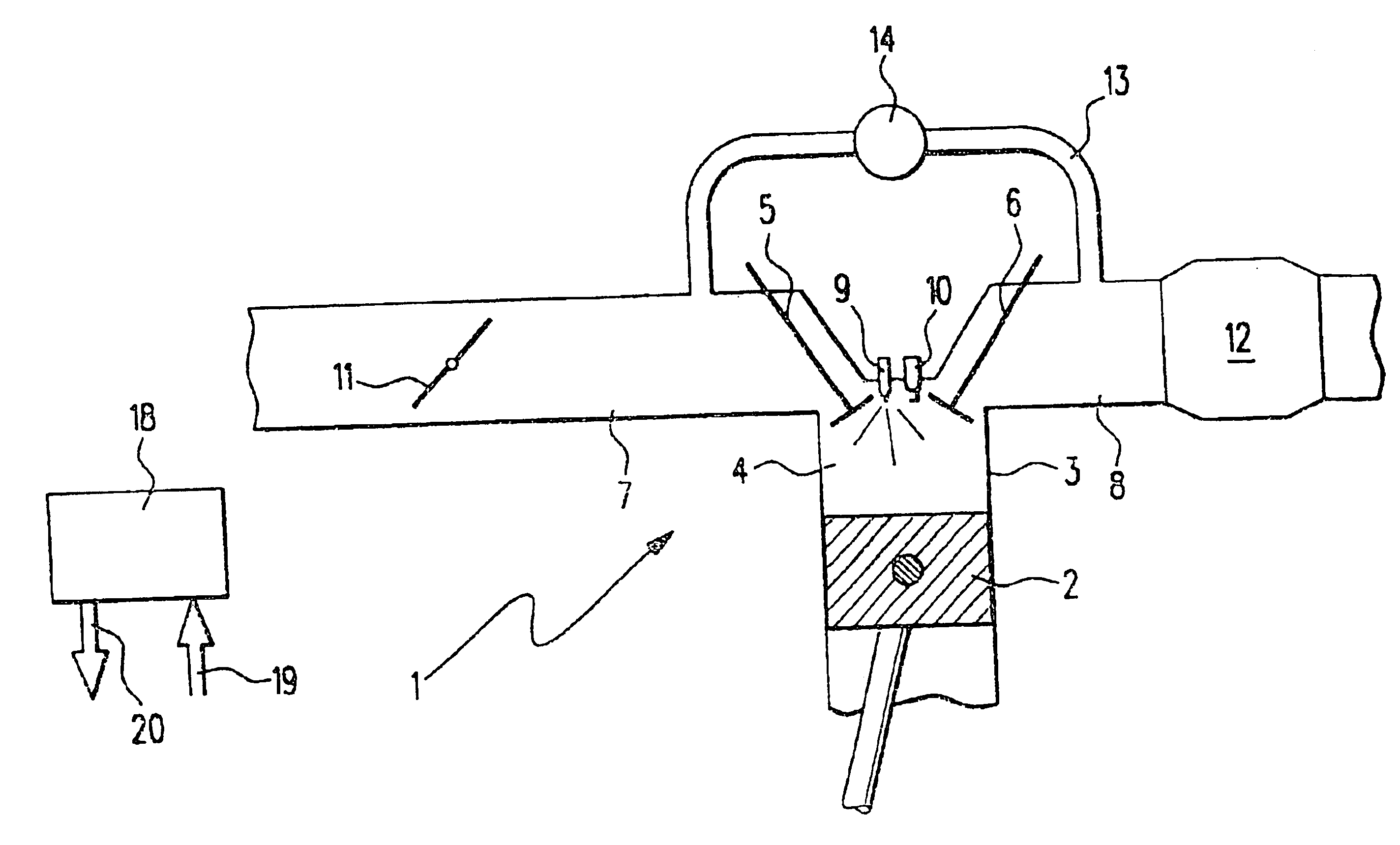
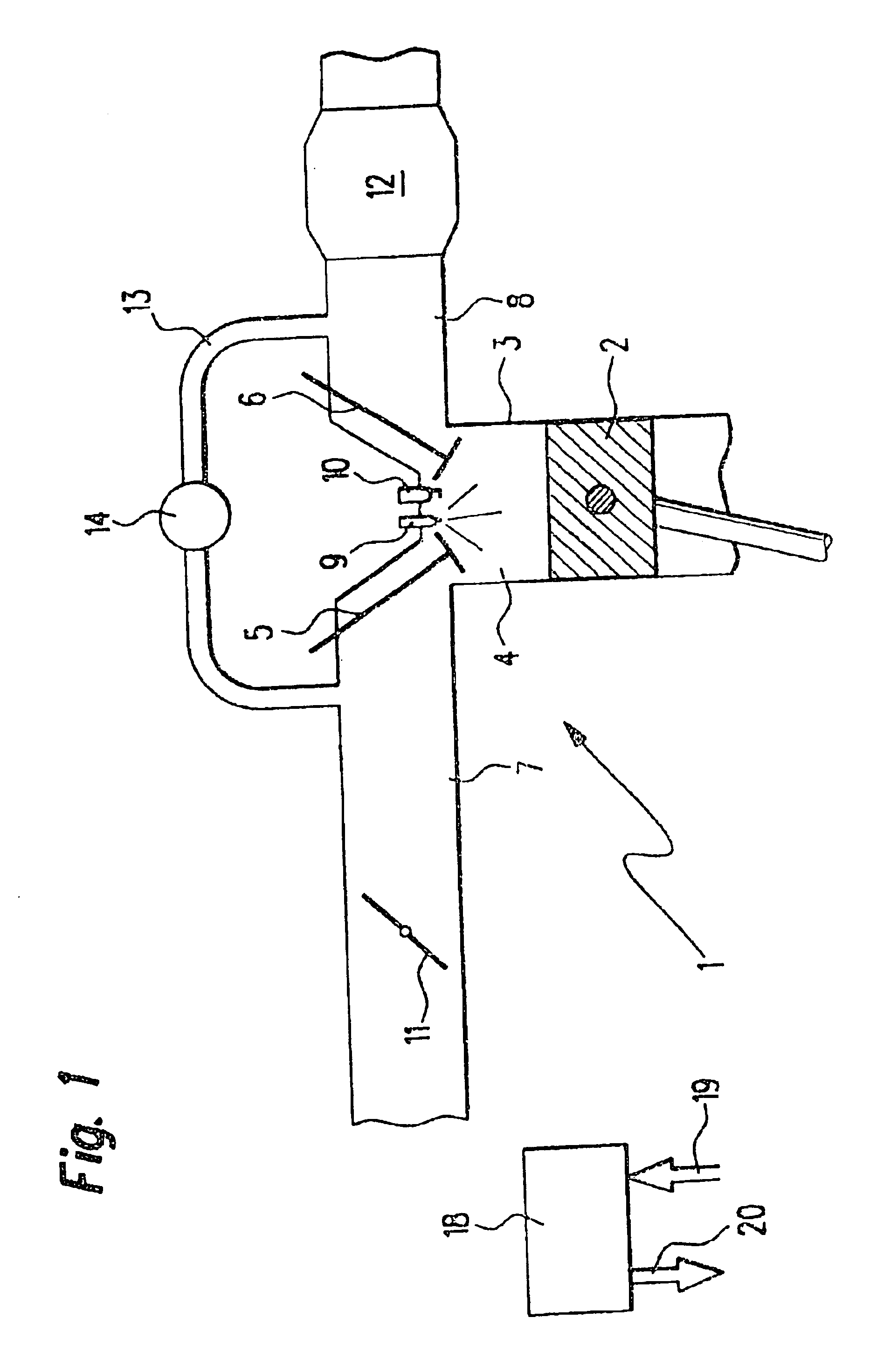
[0018]In FIG. 1, an internal combustion engine 1 of a motor vehicle is shown wherein a piston 2 is movable back and forth in a cylinder 3. The cylinder 3 is provided with a combustion chamber 4 which, inter alia, is delimited by the piston 2, an inlet valve 5 and an outlet valve 6. An intake manifold 7 is coupled to the inlet valve 5 and an exhaust-gas pipe 8 is coupled to the outlet valve 6.

[0019]An injection valve 9 and a spark plug 10 project into the combustion chamber 4 in the region of the inlet valve 5 and of the outlet valve 6. Fuel can be injected into the combustion chamber 4 via the injection valve 9. The fuel in the combustion chamber 4 can be ignited by the spark plug 10.

[0020]A rotatable throttle flap 11 is accommodated in the intake manifold 7 and air can be supplied to the intake manifold 7 via this throttle flap. The quantity of the supplied air is dependent upon the angular position of the throttle flap 11. A catalytic converter 12 is accommodated in the exhaust-ga...


PUM


Abstract

A method for operating an internal combustion engine (1), especially of a motor vehicle, is described. Air and fuel are supplied to a combustion chamber (4) of the internal combustion engine (1) and exhaust gas is recirculated to the combustion chamber (4). The exhaust gas is recirculated to the combustion chamber (4) during overrun operation of the internal combustion engine (1).

Description

[0001]This is the U.S. national stage of International Application PCT / DE02 / 01233, filed Apr. 4, 2002, designating the United States.FIELD OF THE INVENTION[0002]The invention proceeds from a method for operating an internal combustion engine, especially of a motor vehicle, wherein air and fuel are supplied to a combustion chamber and wherein exhaust gas is fed back to the combustion chamber. The invention relates likewise to a corresponding internal combustion engine as well as a control apparatus for an internal combustion engine of this type.BACKGROUND OF THE INVENTION[0003]A method of the above kind, an internal combustion engine of the above kind and a control apparatus of the above kind are generally known from internal combustion engines having exhaust-gas recirculation, for example, from a so-called gasoline-direct injection or a so-called diesel direct injection or also from a so-called intake manifold injection, each having exhaust-gas recirculation.[0004]In these internal ...

Claims


Application Information

Patent Timeline
Patent Type & Authority Patents(United States)
IPC IPC(8): F02D21/00F02D41/12F02D21/08F02M25/07F01N3/24F02D29/00F02D45/00
CPCF02D21/08F02D41/123F02D41/0055Y02T10/47Y02T10/40
Inventor BLUMENSTOCK, ANDREASRIES-MUELLER, KLAUS
Owner ROBERT BOSCH GMBH
Why Eureka
Try Eureka