Method for securing a yoke to a tube using magnetic pulse welding techniques

a technology of magnetic pulse and welding technique, which is applied in the direction of welding apparatus, manufacturing tools, other domestic objects, etc., can solve the problems of undesirable distortion and weaknesses of metallic components, coalescence of two metallic members, and conventional welding techniques that may or may not be performed with pressure,

Inactive Publication Date: 2005-06-28
DANA AUTOMOTIVE SYST GRP LLC
View PDF36 Cites 18 Cited by
  • Summary
  • Abstract
  • Description
  • Claims
  • Application Information

AI Technical Summary

Benefits of technology

[0010]This invention relates to an improved method for performing a magnetic pulse welding operation to secure two metallic components together, such as a yoke and a driveshaft tube in a vehicular driveshaft assembly, that protects the inductor from potential damage that can result from the performance of this operation. The yoke includes a first portion, such as a body portion, and a second portion, such as a pair of opposed yoke arms. The end of the driveshaft tube is disposed co-axially about the body portion of the yoke. An inductor axially is positioned co-axially about the overlapping portions of the end of the driveshaft tube and the body portion of the yoke. The inductor is energized to perf

Problems solved by technology

As is well known, conventional welding techniques involve the application of heat to localized areas of two metallic members, which results in a coalescence of the two metallic members.
Such conventional welding techniques may or may not be performed with the application of pressure, and may or may not include the use of a filler metal.
Although conventional welding techniques have functioned satisfactorily in the past, there are some drawbacks to the use thereof in joining the first and second end fittings to the ends of the driveshaft tube.
This application of heat can cause undesirable distortions and weaknesses to be introduced into the metallic components.
Second, while conventional welding techniques are well suited for joining components that are formed from similar metallic materials, it has been found to be somewhat more difficult to adapt them for use in joining components formed from dissimilar metallic materials.
Third, conventional welding techni

Method used


Image

  • Method for securing a yoke to a tube using magnetic pulse welding techniques
  • Method for securing a yoke to a tube using magnetic pulse welding techniques
  • Method for securing a yoke to a tube using magnetic pulse welding techniques

Examples


first embodiment

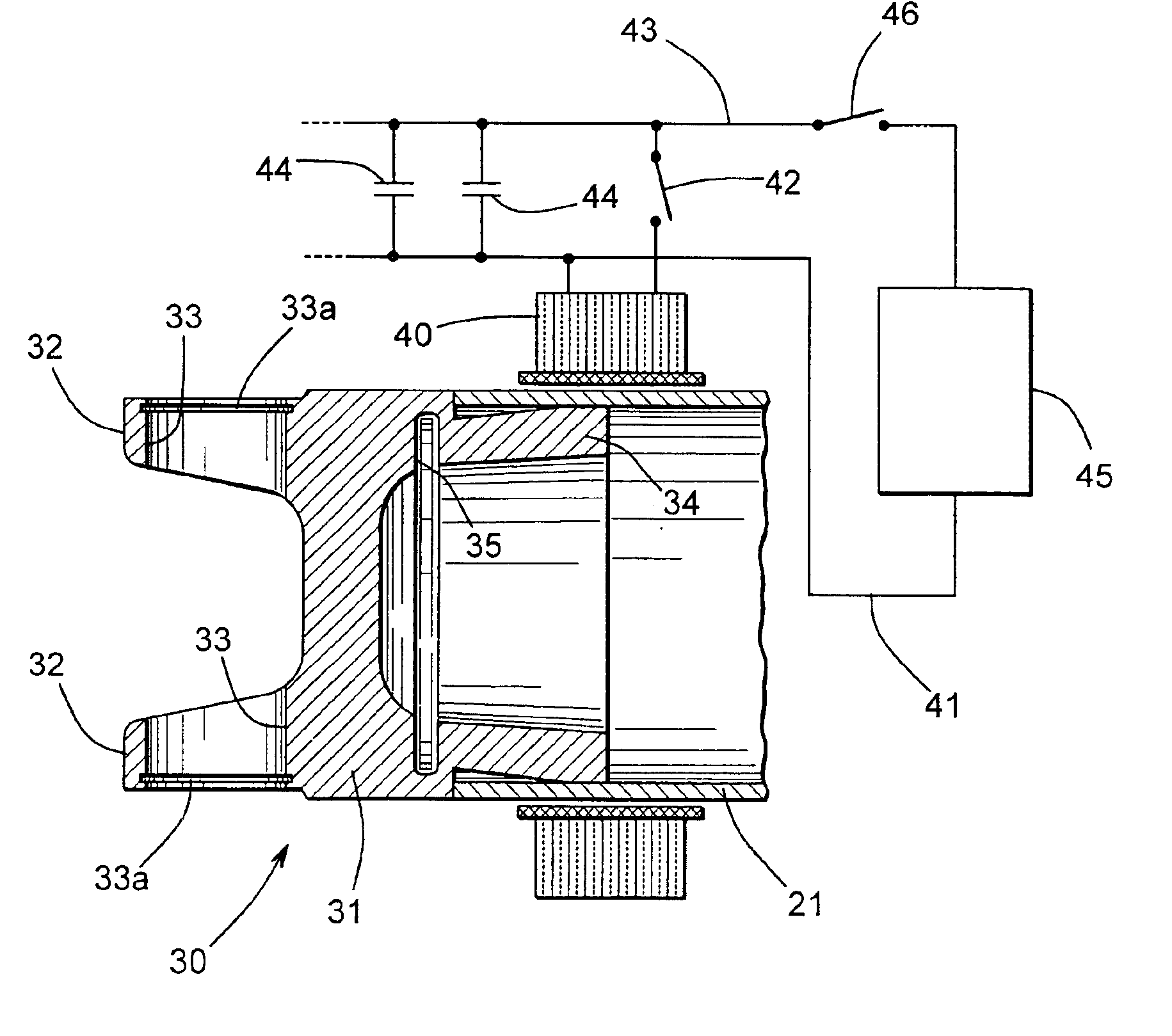
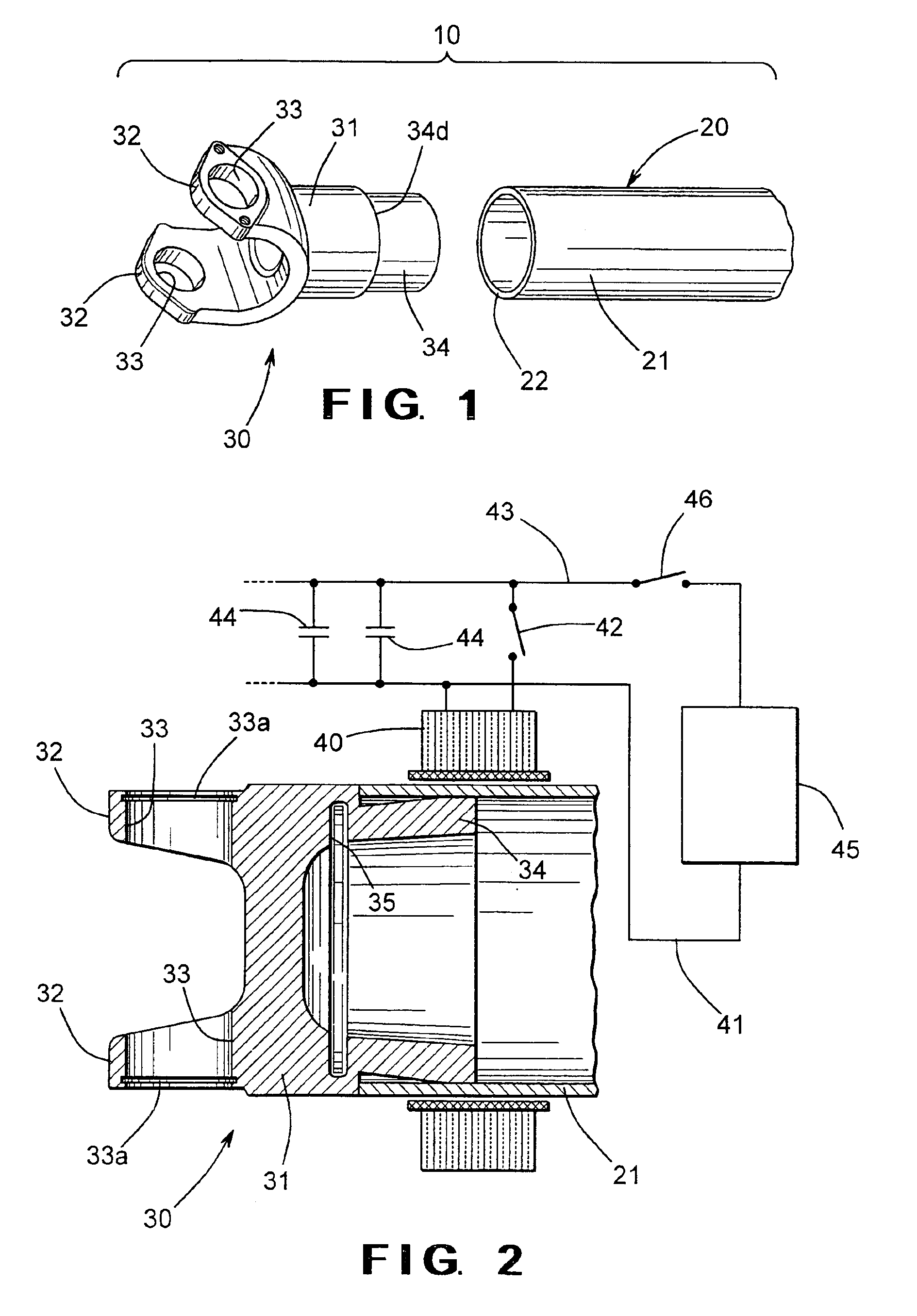
[0025]Referring now to the drawings, there is illustrated in FIGS. 1 and 2 a portion of a vehicular driveshaft assembly 10 that includes a driveshaft tube, indicated generally at 20, and an end fitting, indicated generally at 30. Although this invention will be described and illustrated in the context of securing an end fitting to a driveshaft tube to form a portion of a vehicular driveshaft assembly, it will be appreciated that the method of this invention can be used to secure any two metallic components together for any desired purpose or application.

[0026]The illustrated driveshaft tube 20 is generally hollow and cylindrical in shape and can be formed from any desired metallic material, such as 6061 T6 aluminum alloy, for example. Preferably, the driveshaft tube 20 has an outer surface that defines a substantially constant outer diameter and an inner surface that defines a substantially constant inner diameter. Thus, the illustrated driveshaft tube 20 has a substantially cylindr...

third embodiment

[0042]To minimize the amount of additional electrical energy to perform the magnetic pulse welding operation, a groove (shown in phantom at 62 in FIGS. 8 and 9) can be formed in the step 60 on the end fitting 30″. The groove 62 can extend continuously about the circumference of the end fitting 30″ or only partially thereabout. Furthermore, the groove 62 can be embodied as a plurality of discontinuous recesses formed about the circumference of the end fitting 30″. The purpose of the groove 62 is to mechanically weaken the step 60, thereby allowing the step 60 to be more easily deformed when the magnetic pulse welding operation is performed. Such deformation will minimize the amount of additional electrical energy to perform the magnetic pulse welding operation, while still providing the step 60 for better containment of the air and cumulative flow in the annular space 61.

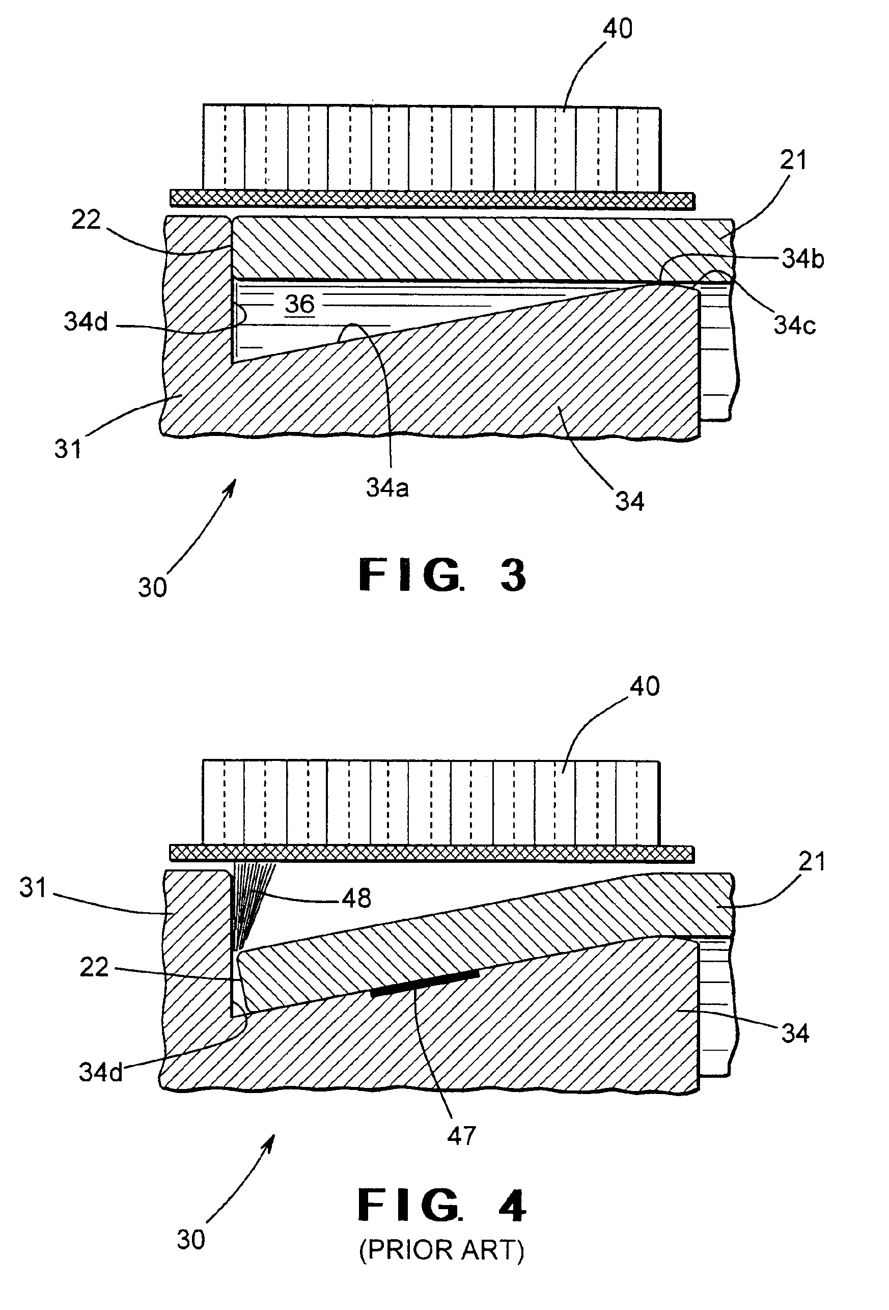
[0043]FIG. 10 is an enlarged sectional elevational view similar to FIG. 3 showing a fourth embodiment of the end f...


PUM


Abstract

A magnetic pulse welding operation is performed to secure first and second metallic components together, such as a yoke and a driveshaft tube in a vehicular driveshaft assembly. The yoke includes a first portion, such as a body portion, and a second portion, such as a pair of opposed yoke arms. The end of the driveshaft tube is disposed co-axially about the body portion of the yoke. An inductor axially is positioned co-axially about the overlapping portions of the end of the driveshaft tube and the body portion of the yoke. The inductor is energized to perform a magnetic pulse welding operation to secure the end of the driveshaft tube to the body portion of the yoke without generating a significant flow of air toward the inductor.

Description

CROSS REFERENCE TO RELATED APPLICATION[0001]This application claims the benefit of U.S. Provisional Application No. 60 / 362,215, filed Mar. 6, 2002, the disclosure of which is incorporated herein by reference.BACKGROUND OF THE INVENTION[0002]This invention relates in general to the use of magnetic pulse welding techniques to secure two metallic components together, such as a yoke and a driveshaft tube in a vehicular driveshaft assembly. In particular, this invention relates to an improved method for performing such a magnetic pulse welding operation that protects the inductor from potential damage that can result from the performance of this operation.[0003]In most land vehicles in use today, a drive train system is provided for transmitting rotational power from an output shaft of an engine / transmission assembly to an input shaft of an axle assembly so as to rotatably drive one or more wheels of the vehicle. To accomplish this, a typical vehicular drive train assembly includes a hol...

Claims


Application Information

Patent Timeline
IPC IPC(8): B23K13/01B23K13/00B23K20/06
CPCB23K20/06B23K2203/10B23K2201/06B23K2101/06B23K2103/10
Inventor YABLOCHNIKOV, BORIS A.
Owner DANA AUTOMOTIVE SYST GRP LLC
Why Eureka
Try Eureka