Antiseptic preoperative applicator

a pre-operative and anti-bacterial technology, applied in the field of liquid applicators, can solve the problems of clogging, affecting the operation, and the tip of the ampoule being broken, so as to improve the anti-bacterial applicator, avoid the necessity, and eliminate accidental opening or rupturing the seal of the vessel

Inactive Publication Date: 2005-06-28
DFB TECH
View PDF6 Cites 50 Cited by
  • Summary
  • Abstract
  • Description
  • Claims
  • Application Information

AI Technical Summary

Benefits of technology

[0006]This invention provides an improved antiseptic applicator useful in patient preparation for surgery. It is an applicator designed for easy dispensation of fluid and yet one which is designed to avoid accidental discharge. At the same time it avoids the necessity of using ampoules. In particular, by employing two integrated components (handle and canister) which cooperate to achieve a product dispensing system, and by retaining these two components by a locking and sealing ring, locking screw and or cam-locking mechanism, the desired product is retained, premature rupture avoided and a unique but simple fluid product holding and dispensing system is realized. In one version of the present invention, the fluid product holding and dispensing system possesses two separate and distinct lock positions, which assures that the system is retained in its locked position, until change is desired by the user. As a result, accidental or unwanted activation of the system is eliminated and users are assured that the product retained and sealed in the container remains sterile and sealed until use is desired. Accidental opening or rupturing of the vessel seal is eliminated. The puncture apparatus for the seal is dual staged and self-venting. The first stage punctures and cuts the membrane seal and then begins to press the membrane / seal back onto the inside of the liquid holding canister. At this point, the second stage of the puncture apparatus contacts the membrane / seal and further opens the previously cut area, thus enlarging the initial opening substantially while causing the membrane / seal to be laid further back into the liquid holding canister. Around the outside of the dual staged puncturing mechanism are vents, which aid airflow into the liquid holding canister. In addition, a flap seal and or form / fill / seal mechanism / membrane could be used to manufacture and seal the canister member of this dispensing system. Finally, by employing the two-component fluid product holding and dispensing trigger assembly of this invention, an easily manufactured, reasonably priced system is attained which is capable of providing consistent, dependable, repeatable results.

Problems solved by technology

The problem with such applicators is that they require breaking of the tip of the ampoule to release antiseptic fluid.
The attendant consequences of having broken ampoule glass are risk of damage to the dispenser allowing glass to contact the patient, risking injury, clogging, and poor flow to the applicator pad or sponge.
However, the problem with current dispensers that use sealing membranes is that the membranes are often subject to accidental rupture resulting in flow of the antiseptic fluid when it is not desired.
However, the solution to the problem expressed in this patent is complex, and high in expense to manufacture.

Method used


Image

  • Antiseptic preoperative applicator
  • Antiseptic preoperative applicator
  • Antiseptic preoperative applicator

Examples


Embodiment Construction

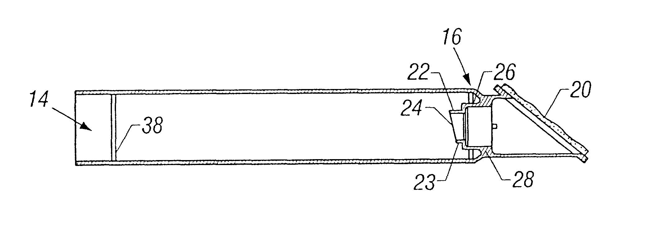
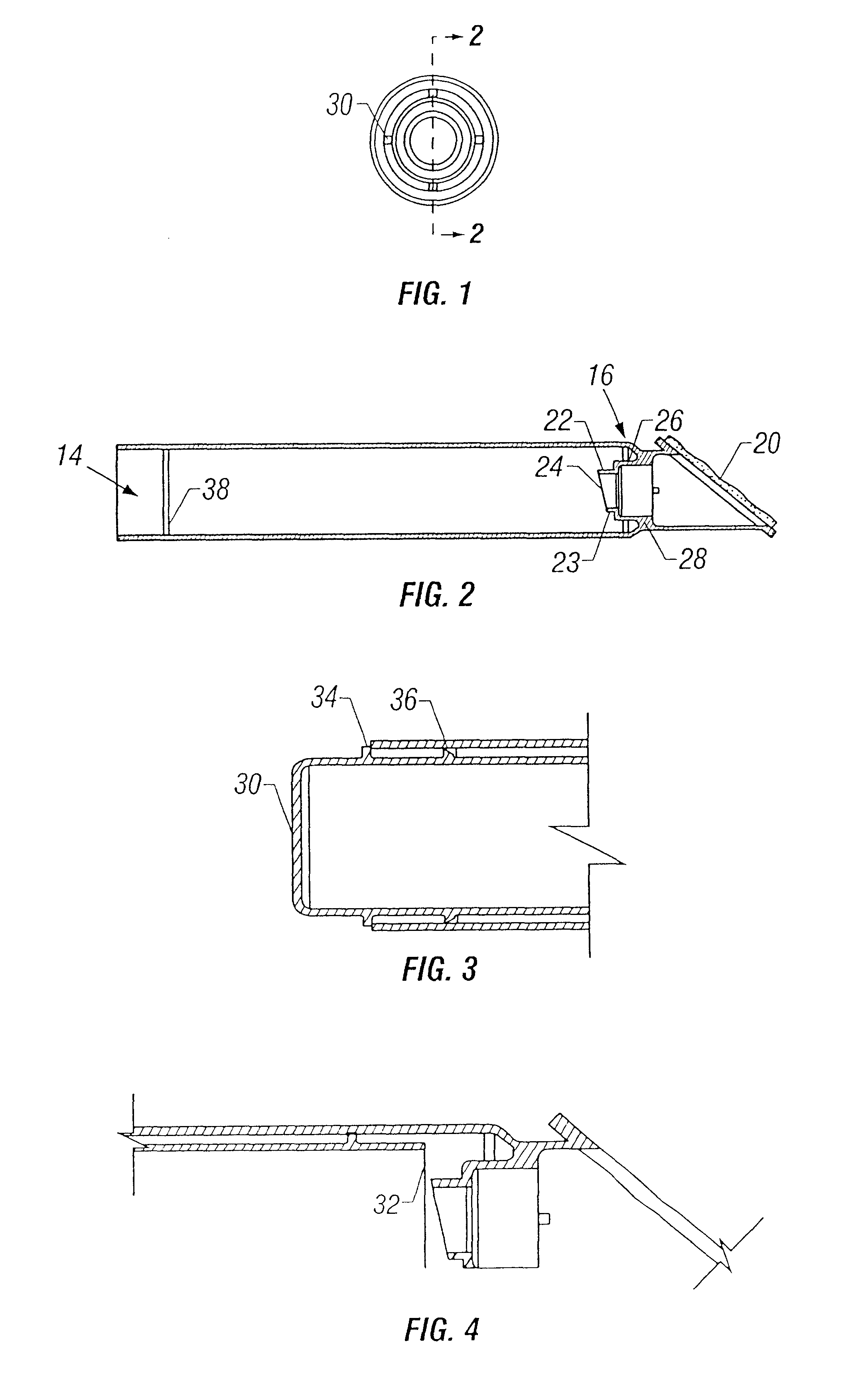
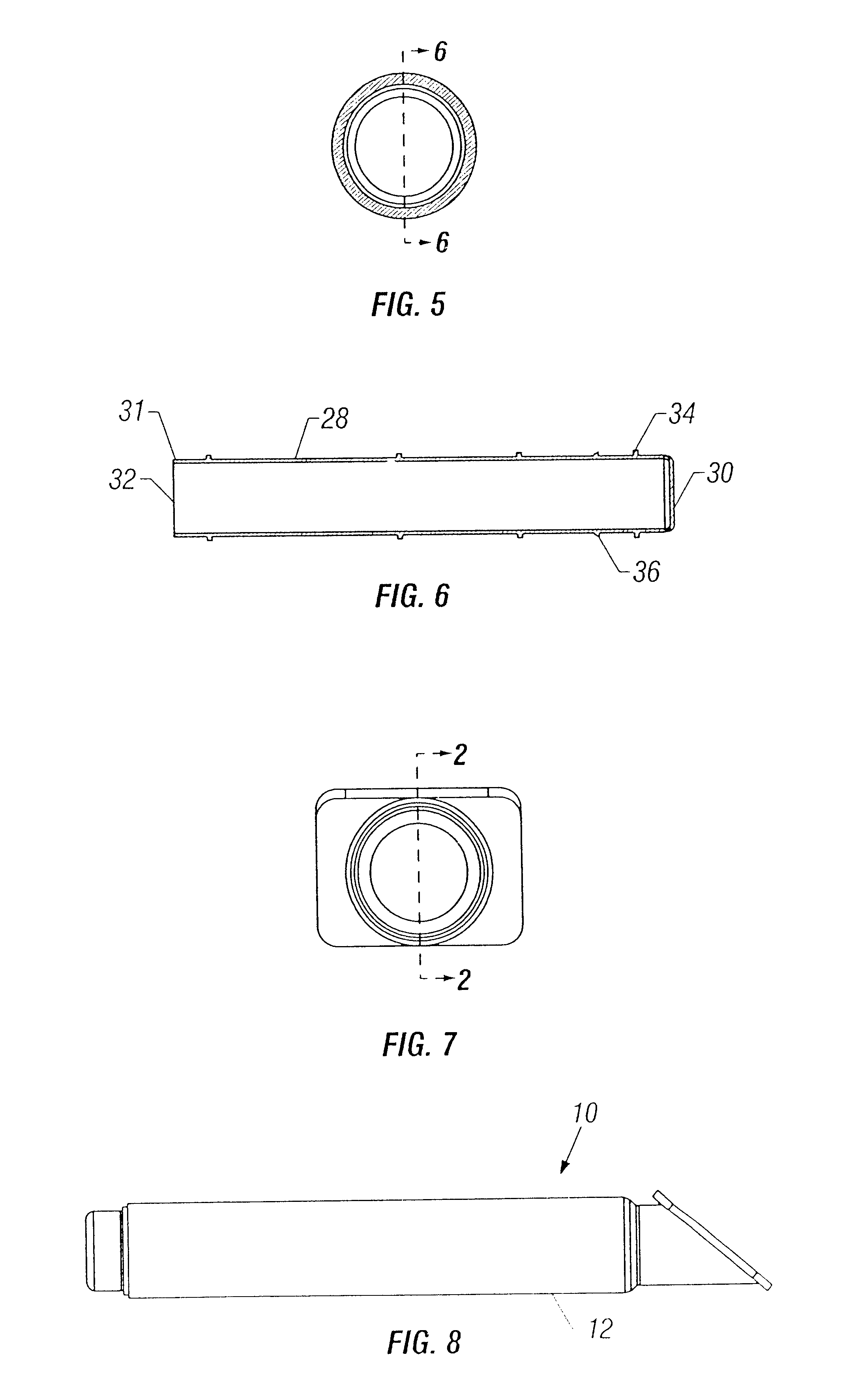
[0017]Turning now to the drawings and particularly to FIG. 8, there is shown an applicator 10 of the present invention. Applicator 10 has a handle portion housing 12 (see FIG. 2) of generally cylindrical configuration. It has a first end 14 and a second end 16. The first end 14 is open exposing the interior of the handle portion. The second end 16 terminates in a neck which at its end has an applicator pad 20 for applying liquid antiseptic. Internally mounted as an integral part of the handle portion housing 12 is a perforator 22 which has a sufficiently sharp edge 23 to allow it to rupture sealed membranes when it pushes against them. Perforator 22 has two stages, a first stage 24 which punctures a sealing membrane and when pushed further against the membrane, the second stage 26 further opens the previously cut area of the membrane 32, thus enlarging the initial hole and causing the membrane seal 32 to be laid further back into the liquid canister 28. The perforator 22 is thus a d...


PUM


Abstract

A liquid dispenser applicator for preoperative preparation of a target area of a patient's skin is comprised of two integrated components, a handle portion and a canister vessel. The two components are locked by a locking and sealing ring mechanism to prevent accidental rupture of the sterile antiseptic fluid in the canister vessel. When the lock is unlocked, the unit contains a perforator designed to initially slit the membrane followed by pushing it open further and thereafter venting it to provide dual-staged self-venting by the perforator for ease of flow.

Description

[0001]This application is a continuation of 09 / 934,142, now U.S. Pat. No. 6,505,985 filed on Aug. 21, 2001.FIELD OF THE INVENTION[0002]This invention relates to liquid applicators, and more particularly, to applicators for preparing a portion of a person's body with antiseptic fluid, often used just before surgery.BACKGROUND OF THE INVENTION[0003]Preparing a person for surgery is commonly called “prepping”. It is typical to scrub the target body portion of the patient with an antiseptic solution. Antiseptic solutions are typically dispensed from a vessel. It is necessary for that vessel to be sterile and sealed prior to use. Commonly employed applicators use an ampoule containing the antiseptic liquid. The ampoule is broken just prior to application. A typical example of such an applicator is that disclosed in U.S. Pat. No. 5,791,801. The problem with such applicators is that they require breaking of the tip of the ampoule to release antiseptic fluid. The attendant consequences of h...

Claims


Application Information

Patent Timeline
Patent Type & Authority Patents(United States)
IPC IPC(8): A61M35/00
CPCA61M35/003
Inventor HIDLE, REX A.GENTRY, SHAWN B.DORMAN, H. PAUL
Owner DFB TECH
Why Eureka
Try Eureka