Connector system for sterile connection

a sterile connection and connector technology, applied in the field of connector systems, can solve the problems of inability to continue peritoneal dialysis, insufficient efficiency, bad prognosis, etc., and achieve the effects of increasing the size of the conventional connector, avoiding contamination, and simple operation

Inactive Publication Date: 2005-06-28
JMS CO LTD
View PDF14 Cites 189 Cited by
  • Summary
  • Abstract
  • Description
  • Claims
  • Application Information

AI Technical Summary

Benefits of technology

[0011]Therefore, with the foregoing in mind, it is an object of the present invention to provide a connector system for sterile connection that enables connection with a simple operation for avoiding the contamination by bacteria, without substantially increasing the size of the conventional connectors.

Problems solved by technology

The most serious problem to be addressed for carrying out the peritoneal dialysis is bacteria in the air or attached to the skin mistakenly entering into the abdominal cavity during the operation of exchanging the dialysis solution as required four times per day.
As a result, for treating the peritonitis, the catheter might be extracted in bad cases, which leads to a situation incapable of continuing the peritoneal dialysis.
Furthermore, the peritonitis repeated for a long term degrades the function of a peritoneum, and as a result, sufficient efficiencies of the dialysis cannot be obtained, or the patient might suffer from sclerosing encapsulating peritonitis (SEP) that is intractable and leads to bad prognosis, including possible death.
However, since these products necessarily require units dedicated to the products, a patient always has to carry the unit.
Moreover, in the event of problems with the unit, serious problems might occur.
In these methods, since a channel for the dialysis solution necessarily becomes open in the connecting operation, it is virtually impossible to prevent the contamination by bacteria.
However, all of those structures have problems in that their mechanism becomes complicated, their size becomes large and the required functions cannot be obtained sufficiently, and therefore none of them have been put into practical use.

Method used


Image

  • Connector system for sterile connection
  • Connector system for sterile connection
  • Connector system for sterile connection

Examples


Embodiment Construction

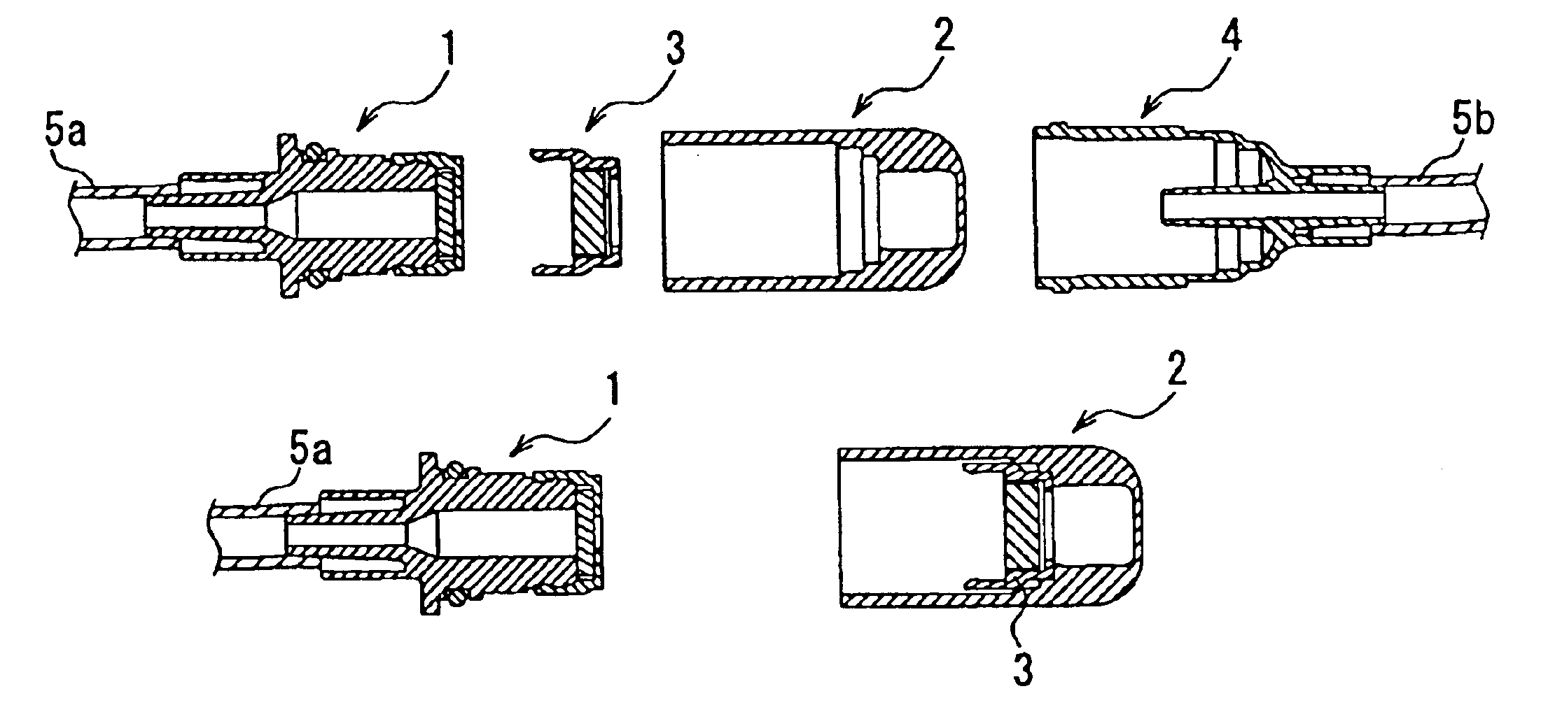
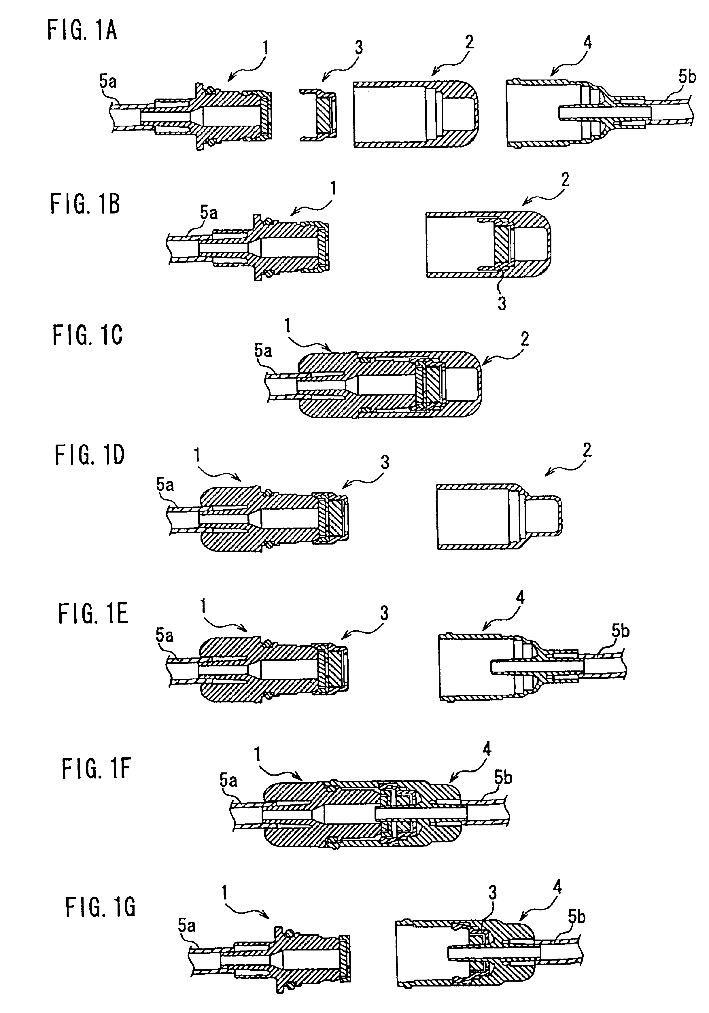
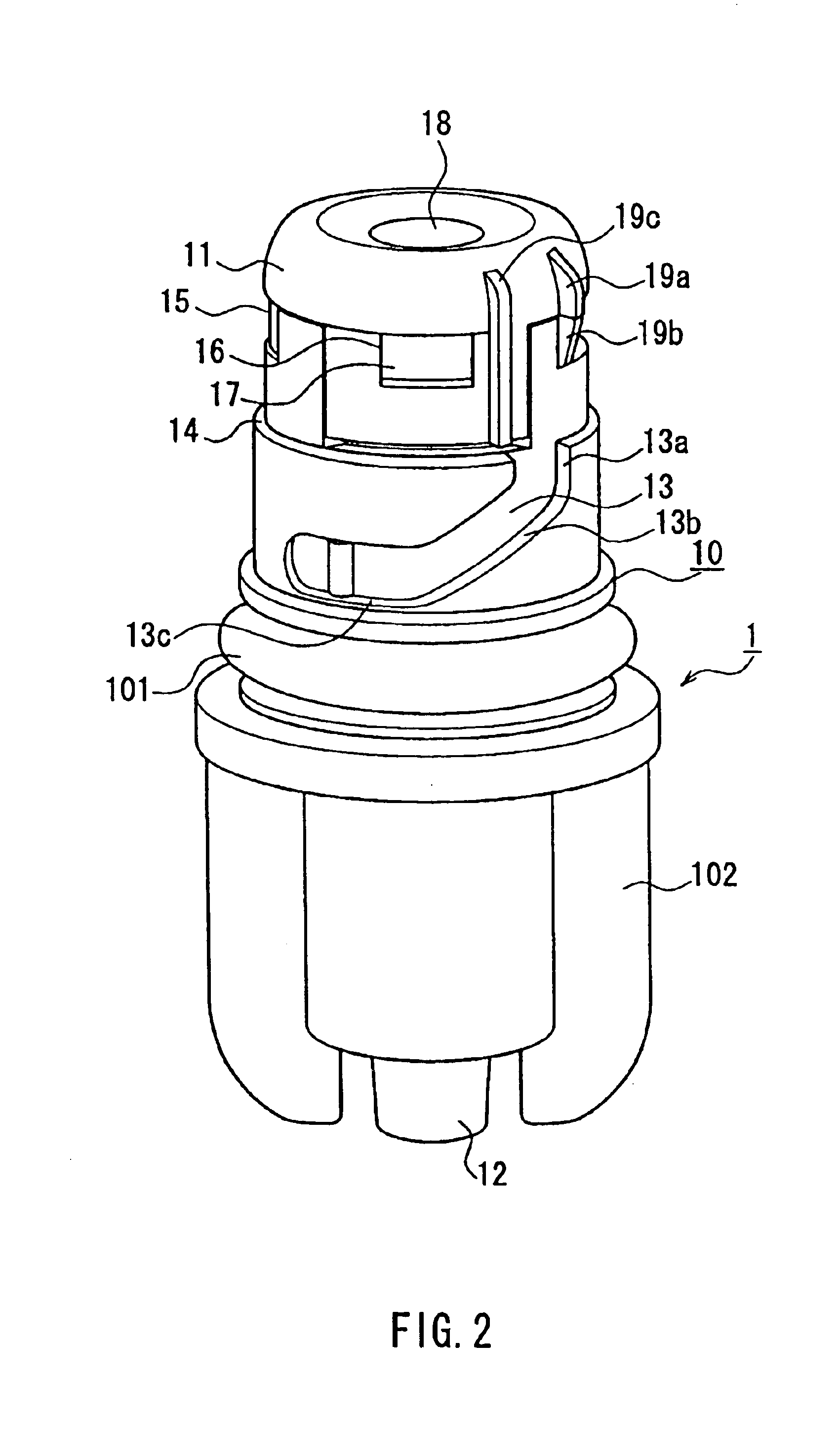
[0034]The following describes a configuration of a connector system for sterile connection according to one embodiment of the present invention, with reference to FIGS. 1 to 7. The present embodiment is described with respect to a peritoneal dialysis system as one example. In this embodiment the male type connector can be considered as on the patient side and the female type connector on the circuit side. “Patient side” and “circuit side” may be used in place of “male type” and “female type” respectively in the discussion of this embodiment. As indicated by an exploded view of FIG. 1A, this connector system for sterile connection includes a patient side connector 1, a protective cap 2, an inner cap 3 and a circuit side connector 4.

[0035]The patient side connector 1 is connected to a front end of an extension tube 5a that leads to a peritoneal catheter implanted in a patient's abdominal cavity. The circuit side connector 4 is connected to an extension tube 5b as a front end of a circ...


PUM


Abstract

A connector system for sterile connection includes a male type connector having a tube connecting portion at a rear end portion thereof, a protective cap for the patient side connector, an inner cap held in the protective cap and including a ring-shaped portion that supports a disinfectant-impregnated member therein, and a female type connector including an outer cylinder and an inner cylinder fixed at one end of the outer cylinder, where the inner cylinder includes an internal end portion located inside the outer cylinder and an external end portion exposed outside the outer cylinder. When the protective cap is fitted with the male type connector, the disinfectant-impregnated member contacts with the male type connector. When the protective cap is removed therefrom, the inner cap becomes retained in the male type connector. When such a male type connector is connected with the female type connector, the internal end portion of the inner cylinder penetrates through the disinfectant-impregnated member and a septum. When the connection is released, the inner cap is detached from the male type connector.

Description

[0001]This application is a continuation-in-part of U.S. application Ser. No. 10 / 353,112, filed Jan. 27, 2003, which is incorporated herein in its entirety.BACKGROUND OF THE INVENTION[0002]1. Field of the Invention[0003]The present invention relates to a connector system, particularly to a system for sterile connection, e.g. as part of a system for conveying fluids to or from a patient. This is useful, for example, for connecting a patient side transfer tube (extension tube) with a container of dialysis solution when a dialysis solution for peritoneal dialysis is exchanged. More particularly, the present invention relates to a connector system for sterile connection provided with a function of securely disinfecting a connecting portion with a simple operation when the connecting and detaching are repeated.[0004]2. Related Background Art[0005]Peritoneal dialysis is a medical treatment method in which a dialysis solution is stored in a patient's abdominal cavity by way of a peritoneal...

Claims


Application Information

Patent Timeline
Patent Type & Authority Patents(United States)
IPC IPC(8): A61M39/00A61M39/16A61M1/28A61M39/10A61M39/14A61M39/20
CPCA61M39/162A61M1/28A61M39/1011A61M39/14Y10S604/905A61M39/20A61M2039/1033A61M2039/1072
Inventor MIYAHARA, HIDEYASU
Owner JMS CO LTD
Why Eureka
Try Eureka